diy solar

diy solar

Classic Norwegian going electric - Polar 22

Tuttifrutti

New Member
Joined
Jan 19, 2021
Messages
38
Greetings from Norway!

I've been lurking around this forum for some time, wondering if I should convert my boat to electric drive or not. Last week I sold my last ICE engine, and now there's no way back!

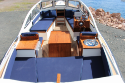
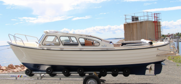
My boat is a classic 22fot Norwegian double-ender, called Polar 22. It has a classic displacement hull and the original engines usually range around 10-20hp. Perfect for electric drive conversion.

So this is my boat! Or what it can end up looking like...Build images are coming in the next post.

Skjermbilde 2021-03-27 kl. 19.33.18.pngSkjermbilde 2021-03-26 kl. 14.30.58.png
 
Last edited:
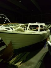
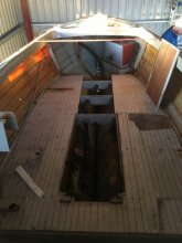
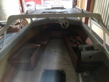
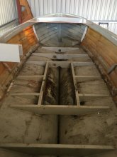
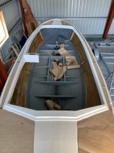
As mentioned above, this is an ongoing project. It originally came with a semi-open solution and worn out interior. I've stripped down the entire boat to the hull itself, cleaned, rinsed and repaired a bunch of details.

It is currently resting at a paint shop, waiting to get a navy blue hull (Ral 5011), and pure white (Ral 9010) top. At the areas where there's brown paper, Isiteek is going to be used, (pvc teak, yeah, I know, not original, but maintenance free) as well as at the bottom of the boat.

IMG_8514.JPG.e4eb166f62ef1fcc4da06e74f7e8ee9a.jpeg149192317_2020-03-1317_41_02.jpg.e08af4356703a14b284c41f967f12c6e.jpg822371357_2020-03-1315_55_54.jpg.7d24234de5141a465b6b2f9c8a665d01.jpg2020-03-21_15_56_39.jpg.f8a88c2c0031de0091f61e6ef3c3c2ca.jpgC33DDD52-8C22-42E8-85E5-3239E11E12B8.jpeg.af78ee34c25b5c9a07b521928ff729a0.jpeg
 
Last edited:
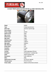
After reading through a couple of threads here, I saw the post regarding engine from an Italian firm. I contacted them and they have been very thorough with their documentation. Comparing their stats on the engine as well as the price, it looks to be a great solution for the boat.

Paired with the ever-so-popular 3,2v 280Ah batteries, this boat should be able to last around 8-10 hours in lounge speed around the Norwegian coastline.


Some stats:
Hull: Displacement hull
Length: 22 feet
Weight: 950kg

Engine:
Fimea N50D2
Rated power: 10kW
Max power:18kW
Rated speed: 1460rpm
Max speed: 3000rpm
Starting torque: 130Nm
Rated current: 240A
Max current: 460A
Rating: IP66
Weight: 59kg
Length: 35cm
diameter: 24cm

Skjermbilde 2021-03-27 kl. 19.54.47.png

Battery pack:
16pcs 3,2v / 280Ah = 48v / 280Ah.


The engine and batteries are estimated to be delivered mid to the end of april, and I'm currently designing the wiring diagram to figure out all the details and equipment needed. Here's where I hope I can get some tips and help from the bright minds on this forum! I'll try to make the diagram as understandable as possible, because I definitely need it to be.
 
Nice work. She'll be a beauty. You're doing it right - from the keel up. Lots of smart folks on here (i'm not really one of them - at least where this project is concerned). Best.
 
Very nice!
(Dunno anything about big motorboats. I'm a kayaker)
Where will you put the panels? Are you going to add a roof?

Don't forget to keep your paddles onboard.
The few eboats I've seen on the water tend to miscalculate occasionally and find themselves "up sh*t creek"
Which is fine as long as there are nice neighbours passing by with ICE boats.
Nice to hear! Kayaker here as well, dads a huge Valley Norkapp enthusiast.

Talking solar panels? If my plan works, I should be able to add flexible solar panels up front and on the canvas roof (when I'm at that stage in the project). I have not calculated the capacity that I can set up here.

Paddles? Yeah. Haven't thought that far ahead to be honest. Tricky boat to row. And i can imagine the satisfaction of an ICE enthusiast pulling an electric boat ?
 
Nice work. She'll be a beauty. You're doing it right - from the keel up. Lots of smart folks on here (i'm not really one of them - at least where this project is concerned). Best.
Thanks! Yeah. Once you start picking stuff apart, its difficult to stop. Fortunately, I should know every nook and cranny of the boat so If anything goes wrong, It should be easy to fix. Ish.
 
If it was mine I'd make a hard roof and cover it with as many panels as I could fit.
I've seen a few YT videos with hobbyists who did this. Reallly ugly but who cares if it works.

Sounds like you're planning on mainly starting out from shore with a good charge on a bunch of batteries.

Hard to paddle, you say? Talk about range anxiety! LOL How about a backup - little gas trolling motor mebbe?
Or do a little rain dance and pray for wind?
 
Y'know it might make some sense to just take along a small gas-powered inverter-generator - (especially on your proving runs) something to add a little oomph to the batteries if things were looking iffy - that assumes you'll have some sort of AC driven charger installed for shore charging. Fairly simple to pull the cord and add to your reserves.
You might even consider a marine rated inverter/charger - matched to your battery bank (handy for making hot coffee, etc.) Best.
 
If it was mine I'd make a hard roof and cover it with as many panels as I could fit.
I've seen a few YT videos with hobbyists who did this. Reallly ugly but who cares if it works.

Sounds like you're planning on mainly starting out from shore with a good charge on a bunch of batteries.

Hard to paddle, you say? Talk about range anxiety! LOL How about a backup - little gas trolling motor mebbe?
Or do a little rain dance and pray for wind?

Well, it used to have a hard roof halfway. However, I wanted to open the boat up to get the classic look. This is also mainly a nice weather lounge boat which in 99% of the cases will be running for 60 minutes tops before it's time to stop, relax and dive into some shrimps. Unless I plan to take it for a longer trip down the coastline. In any case, these trips have to be well planned.

Some marinas are actually starting to set up quick charge solutions for electric boats in Norway, but it has not come that far yet. And range anxiety is always going to be present. I will of course have emergency paddles available. But I sure hope I won't be needing them. ?
 
Last edited:
Just be prepared to hold sheets to the wind, and you can get home under your own power with dignity.


That's amazing! Gotta get some blankets for the emergency kit then. ?

Y'know it might make some sense to just take along a small gas-powered inverter-generator - (especially on your proving runs) something to add a little oomph to the batteries if things were looking iffy - that assumes you'll have some sort of AC driven charger installed for shore charging. Fairly simple to pull the cord and add to your reserves.
You might even consider a marine rated inverter/charger - matched to your battery bank (handy for making hot coffee, etc.) Best.

Good point! I was considering a small generator as a backup in the beginning, but so far, I feel "confident" that It should work. And here's where I hope I can get some assistance from you all.

As I'm currently drawing up the wiring diagram, I'm also trying to figure out which components I should get for my setup. I'll post an overview shortly with the wiring, once I've been able to wrap my head around the concept of chargers, inverters, AC, DC and so on.

Quick rundown:
230V from shore power.
Inverter/charger 230V-48V to LifePo4 battery pack (and to the engine)
Inverter for 48V to 12V (for lights, fridge, equipment etc)

I'm also thinking about having an inverter that can deliver 230V in a plug so that it's possible to charge a computer etc. Not sure if the Multiplus from Victron works both ways(?).
 
Okay. I'm an design engineer. I enjoy technical stuff. But electricity and electrical wiring is something I've struggled with to keep understandable.
So, to better understand the wiring and keep things simple, I'll upload my wiring diagram step-by-step. Might make it easer to investigate one problem at a time.

(Note. Most of what I write here is something I've picked up here and there so its mainly copy paste.)


We'll start at the engine:

Step 1:
Engine has a rated power of 10kW @ 240A, max output 18kW @ 460A.
fcFIlBk.jpg


Step 2:
Engine is connected to the main battery of 48V@280Ah (I'm assuming that a separate start battery is not necessary in a setup like this?). Recommended wiring thickness from the engine spec sheet is 50mm2.
VnCqiR4.jpg


Step 3:
Main battery switch is added at the positive wiring. Keep things safe and all that.

xPx29fS.jpg

Is everything looking a-ok so far? The next step I'll upload will be the Bilge pump, invter, BMS, shunt, battery monitor etc.

(Edit: Updated the images with high-res ones.)
 
Last edited:
Is everything looking a-ok so far? The next step I'll upload will be the Bilge pump, invter, BMS, shunt, battery monitor etc.

Fuse.

Fuse is normally made at least 25% higher rating than maximum continuous current, so it won't blow except in case of overload.

Wire gauge is normally selected to carry current equal to fuse rating without getting hotter than its insulation can take. Sometimes larger gauge to avoid excessive voltage drop due to resistance per foot/meter x length.

240A at rated power, 460A max.
We might want to size based on max current. Given only 280 Ah battery, 460A draw would last about half an hour, so wire doesn't have as much time to heat up. But fuse can certainly blow. You might get away with 460A fuse, but if motor will ever draw that much current, best to oversize 25%, use 575A fuse.

That is a rather large fuse, and large gauge wire. It could be more reasonable to divide into two 300A or three 200A circuits, each with its own fuse.
but if you use multiple wires for negative side, in the event one came lose the others would carry excessive current. Can battery be close enough to motor that a wide busbar could be used for negative?

Note that all busbars between celss also have to carry the 460A draw. Unless you can avoid every carrying more than 240A (OK to have a brief surge starting motor, but not sustained for seconds.)

Is 460A even reasonable for the cells? If you put in two strings of cells, two batteries, they could be fused individually.

Recommended 50 mm^2 is about 1/0. I would use 2/0 cable, which has ampacity 300A in free air for 90 degree C insulation. You can probably get 105 degree C insulation. 300A fuse would be reasonable if current is kept to 240A maximum.

Fuse must be rated not just to blow above 300A, but also for voltage (about 60V fully charged.) And another important rating AIC, Amps Interrupting. If you short-circuit the battery, current will be so high that it can just arc through the fuse and start a fire. Cells have Internal Resistance rating, probably 0.25 milli-ohms maximum, and 0.17 milli-ohms typical measurements. Do the math V/R = I and you'll find it can deliver about 20,000A. Fuse AIC rating needs to be that high. A class T fuse has is rated 20,000 AIC and 125V, sufficient for a single string of lithiu cells. (if two strings, each needs such a fuse.)
 
This. This is exactly why I came here. Thanks @Hedges, I know that I've only scratched the surface here, so I'll update the drawings in a bit with a bit more information regarding wires, fuses etc.

Originally, I was calculating with a smaller engine of around 5kW, which would require a lot less power consumption from the intended battery pack of 280Ah. The engine posted above is actually cheaper than the 5kW solution, which is why I've decided to upgrade the engine. A bit more umpfh is always nice!

Having seen several posts regarding 32pcs @ around 3000$, I might reconsider to upgrade the system to install a battery pack of 560Ah. The boat is not made for speed, and the "ludicrous" mode @460A is rarely if never going to be used, but It is definitely better to build the system after max output.

Follow up question:
What is the correct way to calculate the power consumption of the engine pr hour and the estimated runtime of the batteries?
As you say, "Given only 280 Ah battery, 460A draw would last about half an hour,".

If we follow the classic way to calculate a three-phase electric engine:
W=AV(sqrt 3)
W = 240 * 48 * 1,73 = 19,9kw
 
Last edited:
I was just doing quick math in my head, seeing it was about a 2C discharge rate.
Unlike lead-acid with a large "Peukert" effect, lithium battery capacity isn't much affected by discharge rate. (my home AGM bank, if drained at 1C might last 20 minutes to 70% DoD at least according to low-voltage cutoff)

Decide what SOC range you plan to use, e.g. 10% to 90%. That will tell you how may Ah are available. Voltage varies a small amount; just pick midpoint of discharge curve. I forget if that would be 3.2V or what per cell. Multiply to get watt-hours available.

Not sure how your controller works, if it maintains constant RPM, constant current, constant duty ratio PWM (effectively percentage of battery voltage), or what.

Whether you calculate based on 3-phase RMS voltage and current, or DC voltage and current, depends on the motor or controller specs. Is that "48V, 240A" the DC spec feeding into a brushless DC motor? If so, simple multiplication. But your 3-phase calculation did come close to their 18kW figure.
Could be their maximum 460A 18kW is just when the motor is loaded down to lower RPM and draws more current. Stalled, there is locked rotor amps determined by DC resistance. Rotating, there is a reverse EMF that reduces current draw. Brush-type DC motors reduce current at higher RPM that way. BLDC and VFD are limited by how they control transistors, should be programmed to limit current to a maximum they can handle.

PV panels? You could probably carry 1kW to 2kW of PV panels, hinged to fold on top of each other. If stopped in calm weather, could fold out to do some recharging.
 
I was just doing quick math in my head, seeing it was about a 2C discharge rate.
Unlike lead-acid with a large "Peukert" effect, lithium battery capacity isn't much affected by discharge rate. (my home AGM bank, if drained at 1C might last 20 minutes to 70% DoD at least according to low-voltage cutoff)

Decide what SOC range you plan to use, e.g. 10% to 90%. That will tell you how may Ah are available. Voltage varies a small amount; just pick midpoint of discharge curve. I forget if that would be 3.2V or what per cell. Multiply to get watt-hours available.

Not sure how your controller works, if it maintains constant RPM, constant current, constant duty ratio PWM (effectively percentage of battery voltage), or what.

Whether you calculate based on 3-phase RMS voltage and current, or DC voltage and current, depends on the motor or controller specs. Is that "48V, 240A" the DC spec feeding into a brushless DC motor? If so, simple multiplication. But your 3-phase calculation did come close to their 18kW figure.
Could be their maximum 460A 18kW is just when the motor is loaded down to lower RPM and draws more current. Stalled, there is locked rotor amps determined by DC resistance. Rotating, there is a reverse EMF that reduces current draw. Brush-type DC motors reduce current at higher RPM that way. BLDC and VFD are limited by how they control transistors, should be programmed to limit current to a maximum they can handle.
Yeah. Still not sure how I should set everything up. I've been thinking about having 48V @280Ah mainly for the engine, and a separate 12V @280Ah for the 12V equipment. Not sure how this would work though (everything is calculated based on 3,2V @280Ah LifePo4).

Considering that I've been recommended 4-5kW engines for my boat (runs around 5 knots) from a couple of electric boat engine producers, 10kW-18kW is perhaps a bit overkill. But considering a 5kW engine from Vetus costs around 5500$ and my chosen engine runs for a cool 4000$ for twice the power, the choice seems pretty clear.
I'm probably going to run the engine below rated power for most of the time also. From what I understand, rated power is the most efficient level that the engine can run. Running below rated might not be that efficient?

Heres what Vetus actually recommends in regards to power and boat size: https://www.vetus.com/en/electric-propulsion-product-information

Skjermbilde 2021-03-28 kl. 21.21.42.png
PV panels? You could probably carry 1kW to 2kW of PV panels, hinged to fold on top of each other. If stopped in calm weather, could fold out to do some recharging.
Thats not a bad idea! Been wondering where and how I should store the PV-planels. This is probably something that I have to adjust after using the boat for a bit to see the amount of power consumed as well as the amount of PV panels needed.
 
Last edited:
I re-did the design a bit on the wiring diagram. I have made wiring ready for MPPT and solar panels, BMS, Smartshunts as well, but have not added it to the overall diagram as I want to take it step by step. There's also a jungle of inverters, converters, BMS's etc.

I am looking at the possibility of a complete victron system, but not quite sure about which parts I need.

Here's what I need:

-
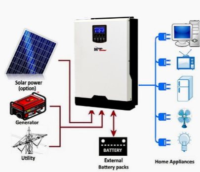
I need a charger that transforms 230V to 48V for my battery pack
- I need an inverter of 48V to 230V to be able to charge a laptop etc
- I need converter of 48V to 12V to run lights, controls, fridge etc. (could be a separate battery pack?)
- I need to calculate a correct MPPT that converts solar to 12V
- I need a BMS that supports the battery pack and overall system

EYUA0Ia.jpg


(Fuses ++++ will be added to the system when I've defined the parts needed)
 
Will has some all-in-ones here but the biggest only goes to 6.5Kw.
 
hello

also located in norway and planning a simular project.
regarding the N50 engine. do you need separate thrust bearing?
no need for 2:1 exchange on engine to axle?
i would dropped solar panels on the polar, just go for a decent (shore) charger.
10kw motor and 14 kwt batterypack is almost overkill in this small boat, but definetly fun!
the small polars consumes roughly about 1kwh in 4 knots, and 2kwh in 5(and so on)
dc-dc to 12 system, or separate battery with small panel and/or small separate 12v charger.
dont see the need for inverting to 220v.
9003e switch and class-t fuse as main.
will follow your project.
 
Back
Top