diy solar

diy solar

Combiner Box - <10A

prtrc

New Member
Joined
Mar 5, 2022
Messages
13
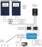
I am down to my final design of a small off grid system for a remote camp. I am leveraging Siemans 110-24P panels that have a ISC of 3.45A and IMP of 3.15A. I was going to use a ECO-PV4 combiner box solution that comes with 10A breakers (10A appears to be the norm). However I am told that your combiner box breakers should not be larger (or too much larger) than your ISC (in my case 3.45A), so design should include a combiner box with no more than 7A breakers. Looking for leads on combiner boxes with breakers of this size - challenge is smallest I can find 10A for each string.

As a backup wondering if I can purchase a 10A combiner box and replace the breakers to a smaller size. To do so I need the breakers, but can't seem to find a supplier of combiner box breakers - they look different than regular house breakers.

Thanks
 

Attachments

  • Ordway Solar Design.JPG
    Ordway Solar Design.JPG
    38 KB · Views: 37
Yeah, not worth it at all. Just use some inline fuses and branch adapters. 2 strings or less usually doesn't require ocpd for each string. Especially with single panels. So you could skip combiner box and fuses, and use just mc4 branch adapters. Add a disconnect switch for convenience. The voltage is so low you could just manually disconnect at solar charge controller input.
 
Thanks for the responses

I am starting with just two strings but likely will graduate up to 4. U

Please confirm fuse size so I am sure. With 3.15 IMP/3.45 ISC per panel, for a two panel system connected with MC4 branch connector - I should use a 7A fuse (3.45 * 2 = 6.9), correct?

Is the general rule the fuse should be as close to your total ISC as possible but not less than your total ISC?

Does the MC4 fuse holder have match the fuse size - in my case 7A - or will a 10A MC4 fuse holder work with a 7A fuse? Not finding anything but 10, 15, etc MC4 fuse holders out there. ,,,,,

I am not likely to do this but want to ask to see if that is OK to do. Location of the fuse compared to branch connector. Based on the above 7A approach the fuse holder would be installed after the branch connector and before the solar controller. But theoretically I could install a 4A fuse connector on each of the + wires out of the panels and before the branch connector - correct (assuming I could find them)?

Thanks
 
If you are connecting two strings in parallel, the fuse should be sized for the string it's protecting. I would recommend a 5 amp fuse, in a 10 amp fuse holder.

Install a fuse holder before the branch connector, on each string.
 
I'm sure I'm missing something but why aren't you putting the modules in series instead of parallel?
 
Combiner box for 3 amps:

solar-mc4-connector-t-branch-2-to-1-splitter-mmf-ffm-pair__1928_580.jpg


https://powerwerx.com/solar-mc4-tbranch-splitter-2to1
 
Yeah, not worth it at all. Just use some inline fuses and branch adapters. 2 strings or less usually doesn't require ocpd for each string. Especially with single panels. So you could skip combiner box and fuses, and use just mc4 branch adapters. Add a disconnect switch for convenience. The voltage is so low you could just manually disconnect at solar charge controller input.
Will, I was about to use combiner box. My configuration is 2s2p with panel Isc -10.19A and Imax 9.62A. The Vmax 33.3V and Voc 40.4V. So, I can skip combiner box and fuse, just use Y splitter? When you said voltage is so low meaning below 100V? Thanks.
 
If you are connecting two strings in parallel, the fuse should be sized for the string it's protecting. I would recommend a 5 amp fuse, in a 10 amp fuse holder.

Install a fuse holder before the branch connector, on each string.
Thanks. As usual for me it leads to additional question(s). My understanding for a parallel wiring solution your amps are a total of all the panels you are wiring together. In my case since I am parallel wiring 2 panels at 3.45A Isc each, my total amperage out of the panels in 6.90amps. So after the branch connectors my amperage is a max of 6.9A. You state a 5 amp fuse. If the fuse will be after the branch connector, and since I am parallel wiring 2 panels at 3.45A Isc, should I not be protecting at 6.90 amps vs 5 amps?

If the answer remains as you stated (5A to protect the individual string), then would the fuse blow after the connector because the Amperage from the combined strings be above 5A, which is 6.90A?

Also I have always assumed that DC amperage is always one way - out from the panels. Are the fuses protecting the panels as well from a unexpected surge back to the panels themselves? One thing I like about a combiner box is the lightning arrester..

Thanks for the patience,
 
I'm sure I'm missing something but why aren't you putting the modules in series instead of parallel?
I have gone back and forth on this one several times in my design. Originally my design was series wired. My panels are 43.5V Voc and 35V Vmp. I will start with just 2 panels but know I likely will graduate to 4 and possibly 6. With that said I want to make sure I size my solar controller accordingly. Since money is not unlimited, I am trying to keep my costs reasonable. Most MPPT controllers in my price range have a Max Solar Input of 100VDC. You increase VDC, you increase price. So trying to stay under that threshold limits me to two panels (35x2=70 ok, 35x3=105 not ok). Understanding that voltage stays the same (35V) in a parallel solution I determined I would wire parallel which keeps me well under the MPPT controllers 100VDC even if I increase the number of panels I have in my system.

If the above logic/understanding is flawed let me know.

Love the question - helps validate I actually understand things correctly.
 
No fuse/breaker needed unless the Isc exceeds the panel short circuit rating. Generally this will not happen until there are at least three parallel strings. The wires have plenty of ampacity to short circuit the panels all day and nothing gets warm.
 
I have gone back and forth on this one several times in my design. Originally my design was series wired. My panels are 43.5V Voc and 35V Vmp. I will start with just 2 panels but know I likely will graduate to 4 and possibly 6. With that said I want to make sure I size my solar controller accordingly. Since money is not unlimited, I am trying to keep my costs reasonable. Most MPPT controllers in my price range have a Max Solar Input of 100VDC. You increase VDC, you increase price. So trying to stay under that threshold limits me to two panels (35x2=70 ok, 35x3=105 not ok). Understanding that voltage stays the same (35V) in a parallel solution I determined I would wire parallel which keeps me well under the MPPT controllers 100VDC even if I increase the number of panels I have in my system.

If the above logic/understanding is flawed let me know.

Love the question - helps validate I actually understand things correctly.
Other than the max voltage of the SCC being based on the Voc, not Vmp, of the the solar modules you seem to have it.

Two modules in series will still work but it's closer than it was. The Voc of a module goes up as temp goes down. It's pretty small but it's not safe to ignore either. Your module will have a published spec but using a generic -3% per degree C you could still run two of the module in series to to at least -10F.

Speaking of published specs. There should a be "max series fuse" rating on the nameplate of your module. You have to know that number before you can determine if it's safe to not use fuses when paralleling modules. Drop "max series fuse" into the forum search bar and you'll find others who can explain it far better than I can.
 
Last edited:
@prtrc , you're going to spend a buttload of money on branch connectors, fuses and fuse holders. That money would be better spent on a good quality solar charge controller that can handle your expansion plans. Do it right the first time.
 
  • Like
Reactions: Rho
What gauge wire should be used from a MPPT solar controller to the battery bank? I will be using 2AWG to wire batteries together in Parallel. Should it be 2AWG from the controller to the batteries or can that be the same gauge wire that runs into the controller from my panels (in my case 10AWG)?
 
What gauge wire should be used from a MPPT solar controller to the battery bank? I will be using 2AWG to wire batteries together in Parallel. Should it be 2AWG from the controller to the batteries or can that be the same gauge wire that runs into the controller from my panels (in my case 10AWG)?
The wire from the scc to batteries is likely thicker than from the combiner since the SCC bumps the amperage up and reduces the voltage meaning thicker wires. Will need ampacity to handle the current and thick enough for voltage loss.
 
What gauge wire should be used from a MPPT solar controller to the battery bank? I will be using 2AWG to wire batteries together in Parallel. Should it be 2AWG from the controller to the batteries or can that be the same gauge wire that runs into the controller from my panels (in my case 10AWG)?

Check the specs on your solar charge controller. My Victron 100/50 is spec'd for a maximum of 6 gauge wire.
 
Back
Top