diy solar

diy solar

Combiner Box - <10A

Check the specs on your solar charge controller. My Victron 100/50 is spec'd for a maximum of 6 gauge wire.
Thanks for this response Boondocker!. Just to clarify on the max gauge wire for controller. My controller specs state 8 AWG Max. So I could use a AWG 8 or smaller (ex: 10 AWG) - but not a a larger size cable (ex: AWG 6). Because smaller the number of the awg wire the bigger the cable is - I just want to make sure I understand "max" correctly. I plan to go with the 8AWG, but want to make sure I understand it fully.

Second question - I want to install several meters on my system, preferably to measure Solar, Charge, Discharge, and Load. I purchased 4 Bayite DC 6.5-100V 0-100A (PZEM-051) meters and was looking at the manufactures wiring diagram (https://images-na.ssl-images-amazon.com/images/I/71vyuArVdSL._SL1500_.jpg). I understand wires from the solar controller to the battery bank, but their diagram also shows wires also connecting directly to the inverter from the controller which surprised me. I reached out to the manufacturer and they stated yes, during the daylight hours the controller will can feed the inverter directly, and any power from the controller not consumed by the inverter goes to the battery. Just wanted to verify this - ok to feed directly from the controller to BOTH the inverter and the battery bank?

Related to the above - if the answer is that it is fine to feed both battery bank and inverter from solar controller:
-- The manufacturer diagram shows feeds to both the battery and the inverter out of the battery output slots on the controller. Since I also have load slots on my solar controller, should I feed the inverter from the "load" slots on my Solar controller, and the battery bank from the "battery" slots on the solar controller? I assume yes. And if yes, I then also feed my inverter from my battery bank, so my inverter will have two input sources as opposed to a single feed just from my battery bank...correct?

Thanks
 
My controller specs state 8 AWG Max
Some SCCs that state 8ga capacity will actually hold 6ga fine. I like oversizing this wire and I’ve got 6ga into a 40A controller that states 8ga capacity in the manual right now. There’s no harm with oversizing this cable if it fits.
 
I reached out to the manufacturer and they stated yes, during the daylight hours the controller will can feed the inverter directly, and any power from the controller not consumed by the inverter goes to the battery. Just wanted to verify this - ok to feed directly from the controller to BOTH the inverter and the battery bank?
Not a problem. THe only issue you could run into is “overcharging the batteries.” This is hard or impossible with lithium, and more of an issue for a FLA battery where they could be limited to max charge of 1/10th the C20 rate. For my 4 large golf cart batteries, this came out to 60 amps.
Since I also have load slots on my solar controller, should I feed the inverter from the "load" slots on my Solar controller, and the battery bank from the "battery" slots on the solar controller? I
The load slot will not handle an inverter, but is designed for low amperage devices. IMO, they provide so little power, they should not be on SCCs. The only time a load could be useful is some can run a low amperage light at a programmed time, or will shut off a load once the battery drops to a certain voltage.
Some SCCs that state 8ga capacity will actually hold 6ga fine. I like oversizing this wire and I’ve got 6ga into a 40A controller that states 8ga capacity in the manual right now. There’s no harm with oversizing this cable if it fits.
Victron is pretty good at giving the max wire gauge that will fit in heir SCCs. I have a 15 amp SCC that is rated for 12 AWG, and the only way I can get 10 AWG in there is to trim the 7 strand wire strands off one at a time until it fits. Probably not a good practice. Perhaps finely stranded welding wire would fit.
 
Put this in google or whatever you use. I use to have a link but can't find. Years ago on another forum a poster did what you did, it ended up burning his controller. I was trying to fing the thread, if I do I'll post it.

12 awg to 10 awg crimp reducer
 
Thanks for this response Boondocker!. Just to clarify on the max gauge wire for controller. My controller specs state 8 AWG Max. So I could use a AWG 8 or smaller (ex: 10 AWG) - but not a a larger size cable (ex: AWG 6). Because smaller the number of the awg wire the bigger the cable is - I just want to make sure I understand "max" correctly. I plan to go with the 8AWG, but want to make sure I understand it fully.

You have it right. The smaller the number, the larger the size of the wire.

I used 6 gauge coming out of the solar charge controller. It's the largest gauge that Victron's specifications said would fit. For the distance, voltage and amperage, 6 gauge is more than enough wire. 8 gauge is likely fine for your situation, as long as you don't have a long distance run. Be sure to use a wire gauge calculator to confirm that.

Second question - I want to install several meters on my system, preferably to measure Solar, Charge, Discharge, and Load. I purchased 4 Bayite DC 6.5-100V 0-100A (PZEM-051) meters and was looking at the manufactures wiring diagram (https://images-na.ssl-images-amazon.com/images/I/71vyuArVdSL._SL1500_.jpg). I understand wires from the solar controller to the battery bank, but their diagram also shows wires also connecting directly to the inverter from the controller which surprised me. I reached out to the manufacturer and they stated yes, during the daylight hours the controller will can feed the inverter directly, and any power from the controller not consumed by the inverter goes to the battery. Just wanted to verify this - ok to feed directly from the controller to BOTH the inverter and the battery bank?

Think if your system as a pool of water. The solar charge controller is putting water into the pool. The battery and inverter are drawing water out. The inverter is capable of drawing more water than the battery. If your solar charge controller is pushing 1000 watts into the system and the inverter is pulling 1000 watts then there is no power going to the battery. If the inverter is only drawing 500 watts then the battery gets 500 watts for charging.

I'm not convinced that you need the meters. The solar charge controller should be able to report this information. The inverter and BMS can do that same.

Related to the above - if the answer is that it is fine to feed both battery bank and inverter from solar controller:
-- The manufacturer diagram shows feeds to both the battery and the inverter out of the battery output slots on the controller. Since I also have load slots on my solar controller, should I feed the inverter from the "load" slots on my Solar controller, and the battery bank from the "battery" slots on the solar controller? I assume yes. And if yes, I then also feed my inverter from my battery bank, so my inverter will have two input sources as opposed to a single feed just from my battery bank...correct?

As @chrisski said, the load slots are for small loads. My Victron SmartSolar 100/50 solar charge controller does not have load ports. If it did come with a load port, I suppose I would find something to use it for. My PWM solar charge controller has a USB port. I don't think it's considered a load port as it is active at all times, not just when the sun is out.
 
Put this in google or whatever you use. I use to have a link but can't find. Years ago on another forum a poster did what you did, it ended up burning his controller. I was trying to fing the thread, if I do I'll post it.

12 awg to 10 awg crimp reducer
I’m looking for a recommendation of a reducer someone has used. A few of the thingsI got from google I’ve been upset about.

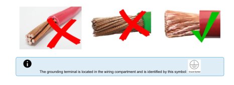
In Victron’s SCC manual for their larger 48 volt units, they want many stranded wire so when the set screw is tightened it is crushed flat to get a good contact area. I think these reducers would do just the opposite And the same thing with wire end caps (ferrules?).

I do not recommend trimming down wire and inserting it to the controller. I did this on a 15 amp controller for my crate build. Something that gets set up in the yard and if it did burn down would not take the house down. I would not d this in my RV. Cutting ends off wire is at best a really poor proactive.
 
In Victron’s SCC manual for their larger 48 volt units, they want many stranded wire so when the set screw is tightened it is crushed flat to get a good contact area. I think these reducers would do just the opposite And the same thing with wire end caps (ferrules?).

I did use ferrules on the wires going into and out of my Victron 100/50. 6 gauge welding wire, 6 gauge ferrules. So far, so good.
 
I did use ferrules on the wires going into and out of my Victron 100/50. 6 gauge welding wire, 6 gauge ferrules. So far, so good.
I have used seven strand wire in my three SCCs in my RV for a year with no issues. 7 Strand does not crush flat. I’m not going to replace my wiring because of what is in the manual and I’m not going to lose any sleep over it either.

I’m not even sure what I’ll do for my next build since the solar PV wire I buy only comes in 7 strand, and occasionally 12 strand. I’m sure there is multistranded wire rated for direct exposure to the sun, but I have not found it. I do wonder if the many stranded wire like Victron recommends would need to get installed in conduit,
 
I’m not even sure what I’ll do for my next build since the solar PV wire I buy only comes in 7 strand, and occasionally 12 strand. I’m sure there is multistranded wire rated for direct exposure to the sun, but I have not found it. I do wonder if the many stranded wire like Victron recommends would need to get installed in conduit,

This is the PV wire I used. 19 strand.

 
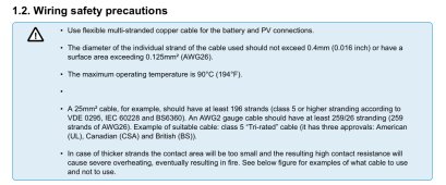
Victron asks for 196 strand wire for 25 mm2. I think that is 4 AWG, and for 6 AWG, that should be 98 stand. Seems Victron wants us to use welding wire to attach wires to the SCC. Perhaps the class 5 rating to me means finely stranded enough for a Victron SCC. Notice the warning about fire if not used correctly. This is from Victrons manual for the charge controllers that include a 100 amp version.

This is something had I read this prior to my install, I probably would have spent a week of man hours figuring out what I want to do.

F38CB1AE-C3F6-48B5-B80E-4A8B6BDBA47C.jpeg
6B6BACEF-DA73-48F2-A9AA-21A03EB02D4E.jpeg
 

The pictures in that thread are similar to what I saw on my Xantrex ProWatt 1000 inverter last year. Something happened to the negative terminal that the 1 gauge cable went into. It was NOT finely stranded cable. I didn't know any better at the time (4 years ago) and bought the required 1 gauge cable from Home Depot. It was very stiff stuff. I didn't have sufficient strain relief on the cable. The scorching/melting at the terminal prompted me to take the (perfectly working) inverter out of service and upgrade to the Victron Multiplus 12/3000.

I do not like screw down terminals. I prefer a stud that I can put a lug on.
 
Some scary stuff when it comes to electricity. Everything looks ok till it's not.
 
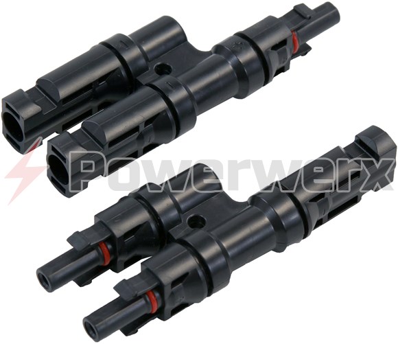
Combiner box for 3 amps:

solar-mc4-connector-t-branch-2-to-1-splitter-mmf-ffm-pair__1928_580.jpg


https://powerwerx.com/solar-mc4-tbranch-splitter-2to1
Most MC-4 products (I have found) have a Protection Rating: IP67.

If you really need to use something similar, you may want an IP68 rated product.
 
Is this rated to leave in the sun, do you take it down, or in conduit or something elde
Plastic slinky cover for outside.
Although the first 8ga cable went 3+ years with only color degradation.

And now it’s new 6ga, inside, SCC to busbar as a have exceeded 40A as expected.
 
You have it right. The smaller the number, the larger the size of the wire.

I used 6 gauge coming out of the solar charge controller. It's the largest gauge that Victron's specifications said would fit. For the distance, voltage and amperage, 6 gauge is more than enough wire. 8 gauge is likely fine for your situation, as long as you don't have a long distance run. Be sure to use a wire gauge calculator to confirm that.


Think if your system as a pool of water. The solar charge controller is putting water into the pool. The battery and inverter are drawing water out. The inverter is capable of drawing more water than the battery. If your solar charge controller is pushing 1000 watts into the system and the inverter is pulling 1000 watts then there is no power going to the battery. If the inverter is only drawing 500 watts then the battery gets 500 watts for charging.

I'm not convinced that you need the meters. The solar charge controller should be able to report this information. The inverter and BMS can do that same.


As @chrisski said, the load slots are for small loads. My Victron SmartSolar 100/50 solar charge controller does not have load ports. If it did come with a load port, I suppose I would find something to use it for. My PWM solar charge controller has a USB port. I don't think it's considered a load port as it is active at all times, not just when the sun is out.
Finally have my system functional today after some delays. I have it hooked up here at home as a dry run (did not use a combiner box for now since only 2 panels) , and when the roads dry out I will set up at my remote camp. Thanks for all the input so far from various contributors.

Something did surprise me today when I first connected everything - the amperage seemed much higher from the panels to the controller than I expected. As a reminder my panels are 3.15 A IMP, 3.45 A ISC. I have my panels wired in parallel, so I was expecting 6+ amps at the solar controller. While my panels were in direct 100% sunlight, the controller was showing 12.5+ amps from the panels. I had to run an errand so I disconnected the panels at the connectors, and reconnected on my return. The sun was intermittent at that time (60/40 clouds to sun) so now I'm running around 1.75 amps to the controller from the panels. Voltage is running around 38 (panels are VMP 35 VOC 43.5). I have a second (Charge) and third (Discharge) meter wired after the battery bank and before inverter and it reads basically the same amperage.

Why in direct sunlight was the amperage so high?

BTW - Panels are 10A rated so I have a10A fuse on each + wire coming from the panels. As stated overkill for my current 2-panel set up but I will be expanding the number of panels once at my remote camp.

Thx
 
Back
Top