diy solar

diy solar

Combiner box?

iamrich

Solar Addict
Joined
Dec 17, 2020
Messages
1,175
Location
Elgin, Texas
Just starting out with solar and have so many questions. I have been reading as much as I can and looking for similar setups to emulate, but coming up short on a few questions.

I am building a small setup to power my garage off grid with x9 250w panels on the roof feeding a 24V Hybrid LV2424. I plan to run them 3S3P. What are my options for connecting these into the controller?

Panels are 250W, 37.6v VOC, 8.27A
Controller is good to 145VDC input, 80A
Metal Roof facing Southeast (more east than south unfortunately)
Temp never gets below 0F, rarely below 30F

Panels:
Rated Power: 250W
Open circuit voltage (VOC): 37.6 V
Max power voltage (VMP): 30.3 V
Short circuit current (ISC): 8.85 A
Max power current: 8.27 A
Power Tolerance 0/+3%
Maximum system voltage: 600V (UL)
Fuse Rating: 15 A
IP65 Junction Box w/MC4 Compatible Connectors

Hybrid LV2424:
2000 W MPPT charge controller (30 to 115V PV Vmp DC Voltage – max 80A)
 
You can get an MC4 "Y" cable of suitable gauge for the current from panels.
More than two strings of panels in parallel, so fuses for each. You can get MC4 fuse holders.

Combiner box is the other way, either breakers or touch-safe fuse holders.
Single-pole breaker good for 150V are common.

Many of these breakers are polarized, only interrupt current without burning when wired in the correct orientation. If those are used I would like to see all ganged together, e.g. with a stiff wire slid through hole in their handle. Maybe they can be bought pre-ganged (3PST).
The vendors claim polarized breakers work for PV disconnects, but they have to interrupt current in one direction under normal operation and reverse direction in the event of a fault (one string of PV shorted). So I say individual polarized breakers are not good.

You can find ready-made combiner boxes on eBay, Amazon, retailers of Midnight Solar products. Or any waterproof box with DIN rail inside.

Fuse holders aren't for disconnecting with current flow. If there is a switch/breaker for the combined wire, or a breaker between charge controller and battery, that will turn it off.
MC4 fuse holders aren't touch-safe. Disconnect both ends from MC cable before opening to access fuse.
 
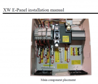
I use this Midnight 6-breaker combiner. They make a 3-breaker model, but plan ahead and expect to expand your system later. I've already filled up all 6 spots with my own system.
1609352181544.png


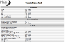
I plugged your values into Midnight's string calculator. Looks like this configuration is good even below 0F.
1609352045806.png
 
Thanks for the reply.

You can get an MC4 "Y" cable of suitable gauge for the current from panels.
More than two strings of panels in parallel, so fuses for each. You can get MC4 fuse holders.

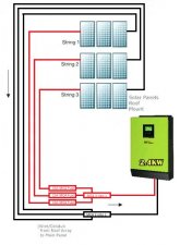
Do you see any danger in bringing the three lines (6 wires) into the garage through Sch 80 conduit and then just using a 3 into 1 MC 4 on the neutral side, and a 15amp MC4 fuse on each string going into a 3 into 1 MC4 and then into the controller. It would use more wire, but then the fuses would be accessible on the ground instead of needing to get on the roof.

3S3P.jpg
 
Sounds good. Make sure "Y" adapter is suitable gauge for the combined current.
A nice thing about separate wire runs for each string is you have more flexibility to reconfigure in the future if you add panels or change inverter.

Run a ground wire for panel frames.

I like over-paneling, extra wattage of PV panels even beyond charge controller ratings, but with some strings at different orientations. The strings can still be paralleled, but will produce lower total peak current and a broader peak for more uniform production over the day.

Various jurisdictions have rules for panels mounted on buildings including disconnects, AFCI, module level rapid shutdown, location of panels. Some of these are to avoid starting fires and some are for safety of firemen.
Your concern for hazards and code compliance may vary.

You might want a disconnect for PV to inverter. Or maybe switching off inverter is sufficient to stop current flow.

You can double-check polarity of pigtail MC4 wires that will go to inverter by connecting to a single PV panel. That way voltage isn't particularly hazardous while you're testing stripped ends with a meter.
I check each series string with meter (careful of high voltage) prior to mating with others, make sure all are same voltage and no net voltage between them.
 
Me personally, am not a big fan of fuses. I myself much prefer breakers, simply for troubleshooting purposes. In the real-world, I've suspected that something was wrong with an array because overall current flow was lower than expected. By flipping breakers on arrays 1 and 2, I could observe no current was flowing on array 3. I was able to track down a broken MC4 connection that took 5 minutes to repair.

Doing the same thing with fuses would be more tedious, and potentially dangerous because of arcing.

Once the individual strings are combined, their amperage adds, so you'll need thicker wire downstream of your "3 to 1" connection. You can use an ampicity table like this one to determine whats safe.
Each string could produce ~8A of current. All three combined would be ~25A. Your panel strings are likely to be 10 gauge copper. The combined string should be at least 8 gauge. If it was my system, I'd use 4 gauge.
 
If you use the MC4 fuses, you can’t disconnect one string at a time. Not a show stopper, but not a way to troubleshoot either.

Also, I like the idea of a power interrupt if it can be worked into the system. A big red handle the fire department pulls in case of fire. I only have an RV build at 1 kw, but if I went much bigger or had cabin or house build with a logical place to put a master interrupt, I’d install one.

I have a set of panels that I planned 24 amps of current combined. I chose 6 AWG for a 10’ cable and 6 AWG for a 40’ cable. More loss on the 40’ cable, and 4 AWG would have been better For the longer cable.
 
Run a ground wire for panel frames.
I hadn't thought of that. I assume I can tie all the panels together and then run one wire to ground? Would this go to a grounding rod or can I tie it into the garage somehow? I plan on running the LV2424 2kw inverter to a small AC sub panel. This is a detached garage (all metal).
 
I tie all the frames together and wire back to ground of my PV inverters and utility ground which includes ground rod. If you don't have one yet, install that and tie to metal garage structure.

At least with all metal it isn't likely to catch fire. PV strings have been known to do that because they are high voltage DC and will sustain a good arc.

If other AC sources are available, might be convenient to have interlocked breakers or other way to switch between inverter and other source.

See what is required to have AC neutral and ground bonded together. (some cheap inverters don't allow that.) Having neutral at zero potential lets GFCI outlets provide the protection they're supposed to.
 
The garage is just an empty shell right now and I don't have grid on the property yet. I doubt I will run grid to the gargage in the future, but my LV2424 does have an AC input feature, so I suppose I could always run a 20amp circuit from the house (when I build it). I think I am probably over doing this little project to just hook up lights, but I am not ready to spend the money hooking into the grid yet and I am having quite a bit of fun.
 
Each string could produce ~8A of current. All three combined would be ~25A. Your panel strings are likely to be 10 gauge copper. The combined string should be at least 8 gauge. If it was my system, I'd use 4 gauge.

I was thinking 12awg (~30 feet) from the 3S panels (~90v/~8.5A) to the combiner box, and then my controller calls for 6awg (~2 feet).
 
Here is a Great calculator for DC wiring, you will see my present numbers for 1 of 3 strings. use Silicone jacketed Solar wire only - 19 strand is best, for Panels.
 
Here is a Great calculator for DC wiring, you will see my present numbers for 1 of 3 strings. use Silicone jacketed Solar wire only - 19 strand is best, for Panels.
Thanks! Calculator says less than 1% for 12 gauge. I can live with that.
 
I have that box and no breaker between the controller and the pv6. I have each series of panels with a breaker.

On a second array, I used a dual pole 30 amp breaker between a homemade combiner and that separate SCC. I have 4 panels in parallel that put out 5.2 amps each.
 
I have that box and no breaker between the controller and the pv6. I have each series of panels with a breaker.
I think that might be the route I take as well. I will have three strings of three (3S3P) going into the box each going into a 15amp breaker and then the combined will go to the LV2424. I am trying to figure out what is critical (breaker/fuse) and what is redundant. I don't mind adding safety, but at some point you are adding breakers to protect breakers to protect breakers.

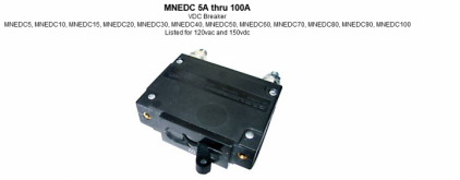
The box I got came with two 30 amp breakers and I was thinking of running the combined through that to the controller, but I read that the breakers are polarized, so I don't think it would offer any protection using them the way I was thinking (sharing the bus bar).
 
The box I got came with two 30 amp breakers and I was thinking of running the combined through that to the controller, but I read that the breakers are polarized, so I don't think it would offer any protection using them the way I was thinking (sharing the bus bar).

With more than two PV strings in parallel, OCP is supposed to protect a shorted string from carrying the current of two or more good strings backfeeding it.
With polarized breakers oriented to interrupt operating current in the normal direction, they are asked to trip under overload in the reverse direction. I believe they are likely to fail.

My proposal is to slip a wire through hole in handles of all the breakers, so if one trips it shuts off the others. The other breakers are carrying current in the proper direction so are able to interrupt current successfully.

With just three strings, 2x Isc is so close to allowed backfeed current I doubt it would actually cause harm to wires or interconnect.
If feeding through failed bypass diodes, those might have higher voltage drop than when in forward operation and at 2x current might overheat.

Although I think a shorted wire could handle 2x Isc, a breaker that couldn't interrupt the current would sit there carrying an arc, dissipating up to the watts of two strings in a small space. (A zero ohm short would carry full current with no power dissipation; all power would be dissipated across the PV string. An unknown impedance somewhere between zero and infinity would dissipate somewhere between zero and maximum array power.)

Besides ganging the breakers, other solutions I propose for polarized breakers are anti-backfeed diodes, or replacing them with either fuses or non-polarized breakers.
 
Back
Top