diy solar

diy solar

Compress or not, flexible busbar or not

I have 48 cells in a 3P16S configuration and I did not use foam or springs. I did separate each group of 3 parallel cells with thin plastic to reduce the chance of voltage leakage if the plastic covering the aluminum shell was compromised.
Yes, definitely use cell separators. I used the PC board material that Docan sent with the cells.

How much force did you assemble your cells with? How many cells in a pack?
 
How much force did you assemble your cells with? How many cells in a pack?
48 cells in a 3P16S. Two rows of 24 cells per row. Six ¼" thread rod. The thread rod was covered with PVC tubing to prevent any voltage leakage between cells. The cells were in compression when I balanced them. Then rearranged and thread rod was retightened. Maybe twenty foot lbs. My goal was to avoid expansion because bus bars connect six terminal in that configuration.
 
When I topped balance all my cells, they were in a fixture. None have mine have been without being in a fixture being charged or discharged.

My battery case has the end plates snug just to prevent any expansion. No springs!
I cannot remember who told me on here but they said if a cell Expands while top balancing then it’s bad from the get go. They also said no compression needed.

I set mine up like Andy and have never had an issue. I am also never charging or discharging above .5 C either.

I believe it’s was @sunshine_eggo but I would have to go way back to find it..
 
Please check your math on this. You only want to use the cross-sectional area of the pieces under expansion force, so don't add the end caps. 2 X 250 X 10 mm = 5000mm^2 is probably what you want if I read your description correctly.
You just calculated the cross-section of the sides of the box. The EVE battery boxes have bottoms and lids too, I assume they welded those too, giving two additional cross-sections of the length of the cell-stack.

For the rods, the cross section is PI X r^2, or 3.141 * 3^2 = 28.27 mm^2.
First, it's not 6 mm rods, but 6 x M14 (14mm, I accidentally wrote M16) rods. Secondly, the threads cut into the cross-section area, thus you can't just calculate it as the cross-section of a cylinder. The M14 has a cross-section of 125mm², which is what I used in the calculation. Calculating it your way it would be 7*7*3.1416=153.9384, or an overestimation of 23% (153.9/125=1.23).

This statement concerns me as well. I don't know how I never saw it. In my defense, it is on the next page after the table, between the header and some Chinese. Every time I read the datasheet I missed this sentence.

The table makes it look like the pressure can be up to 9kN after cell damage. The text clearly says the opposite.

Somebody needs to ask EVE for clarification. I'll check with my taiwanese friend to see if I can get a free translator.

Maybe it renders differently for me, in the LF105 datashee it's at the bottom of p. 27 for me, just below the table. In the LF280K datasheet it's at the top of the page, to the left of the table.

The table might make it seem like that, but it's not just the text I quoted that make it seem like it should be read the other way. The test itself specifies a mm / s value, and it says compression force, not expansion force which they've used for the force generated by the cell itself.

Interestingly enough, if I run the chinese through google translate I get the exact english translations, word for word, that's used in the datasheet. With one exception, where google translates to "battery" it's changed in the datasheet to refer to "cell". I'm starting to wonder who they hired to do the translation..
 
You just calculated the cross-section of the sides of the box. The EVE battery boxes have bottoms and lids too, I assume they welded those too, giving two additional cross-sections of the length of the cell-stack.


First, it's not 6 mm rods, but 6 x M14 (14mm, I accidentally wrote M16) rods. Secondly, the threads cut into the cross-section area, thus you can't just calculate it as the cross-section of a cylinder. The M14 has a cross-section of 125mm², which is what I used in the calculation. Calculating it your way it would be 7*7*3.1416=153.9384, or an overestimation of 23% (153.9/125=1.23).


Maybe it renders differently for me, in the LF105 datashee it's at the bottom of p. 27 for me, just below the table. In the LF280K datasheet it's at the top of the page, to the left of the table.

The table might make it seem like that, but it's not just the text I quoted that make it seem like it should be read the other way. The test itself specifies a mm / s value, and it says compression force, not expansion force which they've used for the force generated by the cell itself.

Interestingly enough, if I run the chinese through google translate I get the exact english translations, word for word, that's used in the datasheet. With one exception, where google translates to "battery" it's changed in the datasheet to refer to "cell". I'm starting to wonder who they hired to do the translation..
Sorry, I didn't realize that you were using bottoms and lids in your calculations. I also missed the part about M14. The threaded rod section is definitely smaller than a similar rod, but I tend to ignore that and use a very conservative value for the strength. Normally you would look for at least 2:1 for working strength anyway, and I was just working on the back of an envelope. Please forgive me.

For my box I didn't even calculate the aluminum bar strength, I just quickly added up the fasteners to make sure they weren't going to shear as soon as I released the compression clamps. My end caps are 1/4" aluminum anyway, and EVE now recommends 5/16". Time will tell.
 
That was a neat solution!
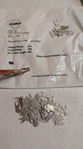
Thanks. Those are PC board tabs. They fit the edges of the bus bars just right after you shove them on. I used a giant solder iron to get heat into the bar quickly enough to get the solder to flow. A little pencil iron won't do it.

PXL_20220923_134856457.jpg
 
Love the idea of the spades and soldering. A lot better than putting the balance leads under the nuts and messing with the torque
Thanks. I agree. The two leads at the positive and negative poles of the battery don't have bus bars, so they still have loop terminals under the nuts, but you do what you can.
 
It’s my understanding that different length balance leads will cause the bms to see the voltages of the cells incorrectly.. many have reported this and some changed to same length wires and the cells all got closer in voltage...
I thought about this more overnight and decided it is worth taking a look.

The impedance of the cell monitoring circuit will be fairly high and will cause almost no current on the wires. That's why the wires can be so small. The only issue might be during active balancing where more current is used to unload high cells while they wait for the lower cells to catch up. Even worse might be an active balancer that attempts to discharge higher cells and charge lower cells with extra balance current. This is all done through the monitor/balance leads.

In my case, my JBD AP20S003S BMSs use an absolute maximum of 260mA for balancing through 24 AWG wires. 24 AWG copper wire should have about 26 Ohms per 1000 feet, or 0.026 Ohms per foot. The longest wire I cut off was 14.5" long, so its resistance is 14.5 X 0.026 = 0.377 Ohms. The maximum voltage difference in that missing length of wire is:

V = I X R -> V = 0.260 A X 0.377 Ohms = 0.098V, or about 10 mV.

I suppose that over time this could make a difference in the top balance since one end of the pack will measure lower than the other, but only while active balancing is occurring. I'll keep an eye on it.
 
Thinking about it even more, the JBD BMSs that I have seem to iteratively drain power from high cells during balancing. It is awfully hard to measure true cell voltage while pulling current through the same wire, so I'm hoping that they only measure cell balance voltage when they are not actually trying to balance that cell. If that is the case, the wire length won't matter at all since the measurement impedance is surely very high (and thus drawing very little current at all).
 
Thinking about it even more, the JBD BMSs that I have seem to iteratively drain power from high cells during balancing.
Yes that is my understanding also. During the pauses between draining power my guess is the same as yours, that is when voltage is measured. I do know that is how my Orion performs on my bigger pack from reading the documentation. I suspect that is how the JBD performs as well.
 
Yes that is my understanding also. During the pauses between draining power my guess is the same as yours, that is when voltage is measured. I do know that is how my Orion performs on my bigger pack from reading the documentation. I suspect that is how the JBD performs as well.
Thanks for confirming that. It wouldn't make sense to me to try to measure while drawing power.

After yet more thought, if this is an issue the JBD design has a serious flaw. They have you pile five leads on cell 14 in a 16S setup. The voltage drop over those five leads would be one fifth of the drop over all of the other leads. Everyone would see cell 14 (in a 16S) unbalancing due to different voltage measurement. I don't think it is an issue at all because I suspect the voltage drop during measurement is a few microvolts.

So it looks like JBD is using 3.6V/0.180A (nominal) = 20 Ohm resistors to bleed power from cells. That means they are pulling about 20 X 0.180^2 = 0.65 Watts from each cell during the balance function. That's not a whole lot, but apparently enough to keep things in balance if everything is in good condition.
 
I cannot remember who told me on here but they said if a cell Expands while top balancing then it’s bad from the get go. They also said no compression needed.

I set mine up like Andy and have never had an issue. I am also never charging or discharging above .5 C either.

I believe it’s was @sunshine_eggo but I would have to go way back to find it..
Top balancing=charging. Why would you not put it in a fixture?
 

In my case, my JBD AP20S003S BMSs use an absolute maximum of 260mA for balancing through 24 AWG wires. 24 AWG copper wire should have about 26 Ohms per 1000 feet, or 0.026 Ohms per foot. The longest wire I cut off was 14.5" long, so its resistance is 14.5 X 0.026 = 0.377 Ohms. The maximum voltage difference in that missing length of wire is:

V = I X R -> V = 0.260 A X 0.377 Ohms = 0.098V, or about 10 mV.

I suppose that over time this could make a difference in the top balance since one end of the pack will measure lower than the other, but only while active balancing is occurring. I'll keep an eye on it.
You have an error. You multiplied 14.5 x 0.026. 14.5 inches = 1.2 feet

You are off by a factor of 12.
 
You have an error. You multiplied 14.5 x 0.026. 14.5 inches = 1.2 feet

You are off by a factor of 12.
Doh. Thanks. That did seem high to me. Always show units!

I also said that 0.098 was about 0.01. All I can say is that I was still drinking my coffee.... If I had recognized the drop as 100 mV I would have known I made an error.

So now we have a piece of wire with 0.031 Ohms resistance giving a voltage drop of about 8 mV.

Math in public....
 
48 cells in a 3P16S. Two rows of 24 cells per row. Six ¼" thread rod. The thread rod was covered with PVC tubing to prevent any voltage leakage between cells. The cells were in compression when I balanced them. Then rearranged and thread rod was retightened. Maybe twenty foot lbs. My goal was to avoid expansion because bus bars connect six terminal in that configuration.
24 cells in a row.. can I see some pics please
 
Thanks for confirming that. It wouldn't make sense to me to try to measure while drawing power.

After yet more thought, if this is an issue the JBD design has a serious flaw. They have you pile five leads on cell 14 in a 16S setup. The voltage drop over those five leads would be one fifth of the drop over all of the other leads. Everyone would see cell 14 (in a 16S) unbalancing due to different voltage measurement. I don't think it is an issue at all because I suspect the voltage drop during measurement is a few microvolts.

So it looks like JBD is using 3.6V/0.180A (nominal) = 20 Ohm resistors to bleed power from cells. That means they are pulling about 20 X 0.180^2 = 0.65 Watts from each cell during the balance function. That's not a whole lot, but apparently enough to keep things in balance if everything is in good condition.
Many threads about just balance/sense wire lengths
 
Many threads about just balance/sense wire lengths
Interesting. I have never read a JK BMS thread since I don't have a JK BMS.
 
Look at it this way: assume each cell is 50 mm thick and it could expand 0.5 mm.

So for one cell, 0.5 / 50 X 100 = 1% change in thickness.

Now consider your pack of 19 cells. The pack is 19 X 50 mm = 950 mm thick and can expand 19 X 0.5 mm = 9.5 mm. The change in thickness is
9.5 / 950 X 100 = 1%.

How can you expect something different to happen when both change by 1% of their thickness? It is the same amount per cell.
I hate to keep bringing this up..
Yes same amount per cell, but as I keep trying to say (and continue to be wrong I guess) that 1% is a longer length of expansion in a 16 cell pack vs a 4 cell pack.. if both packs are in a rigid fixture the walls can’t move out more for the extra expansion distance the pack with more cells needs.. (other than threaded rod stretch which isn’t much), which causes more pressure force roc whatever within the pack...
If the fixture was not rigid and used longer springs to allow for more expansion length for the 16 cell packs then yes there wouldn’t be more pressure building in the 16 cell pack vs the pressure in the 4 cell pack because the springs allows the walls to move out more in the 16 cell pack so the pressure doesn’t build more in the pack with more cells..

But again if expansion is prevented with enough compression then there would be no extra length of expansion or pressure or force with more cells because expansion isn’t happening..
 
Last edited:
Back
Top