diy solar

diy solar

Compress or not, flexible busbar or not

Looks good.
How are you achieving that amount of compression and keeping it constant? I’ve read to much compression is actually worse than no compression. Having the balance wires rings on some nuts and not on others is making the connections from cell to cell different causing different resistance and different cell voltage readings with more one wire ring on some nuts, I guess that’s why I see a lot of the solid busbars tapped (you can’t with braided flexible) so the cells nuts can all be torqued the same without having wire rings on them, so every cell is supplying the same amount of power with same resistance and same bms voltage reading for each cell.. not trying to pick apart your setup, just trying to decide out loud what’s best for me
Yay! I actually saved my notes in case I wanted to build more.
Material List for:
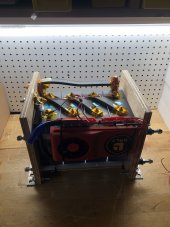
Eight Cell Compression Module
(lithium "Squeeze Box")
Fits most 272/320 Ah Prismatic LiFePO4 cells with allowance for .045" silicone
spacers sheets on wide battery surfaces (9 places).
Home Depot 2' X 4' plywood Sheets, Radiata Pine 1/2"(.480) & 3/4"(.725) thick:
1pc Bottom 3/4" X 7" X 29-1/8"*
2pcs Sides 1/2" X 9" X 29-1/8"*
4pcs Ends 3/4" X 7"* X 8-5/16" (2per end)
2pcs Thrust plate 3/4"X 6-15/16" X 8-1/8"*
*Denotes surface grain direction. Doubled thrust plate has the only vertical grain.
Ends sit on bottom and between sides.
1 pc Spring, 634.6 LB @ .56" deflection
from MSC (mscdirect.com) PN 07661879.
1pc 3/8-16 four pronged Flange nut
1pc 3/8-16 X 3" Bolt, zinc plate (not stainless! it may bend)
1pc 3/8 fender washer, 2pcs 3/8-16 nuts
Grease for threads and washer surface.
Teks sharp point lath screws #8x1-1/4" to align while gluing.
Clamp up assembly squarely before gluing. Drill tight clearance holes through first side
and pre-drill small hole for threads.
Titebond 3 glue, re-coat edges after a few minutes soak in before assembly.
When done, protect with Minwax Helmsman Urethane 3 coats.
Sand between coats, warning very DUSTY!
"Large Silicone Heat Resistant Mat 78.7" X 15.7" (Amazon) (enough for two modules if smart).
Lightly spread a dusting of flower on sides of silicone to help it slide down between batteries,
 
Looks good.
How are you achieving that amount of compression and keeping it constant? I’ve read to much compression is actually worse than no compression. Having the balance wires rings on some nuts and not on others is making the connections from cell to cell different causing different resistance and different cell voltage readings with more one wire ring on some nuts, I guess that’s why I see a lot of the solid busbars tapped (you can’t with braided flexible) so the cells nuts can all be torqued the same without having wire rings on them, so every cell is supplying the same amount of power with same resistance and same bms voltage reading for each cell.. not trying to pick apart your setup, just trying to decide out loud what’s best for me

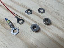
You’re not picking anything apart, but making valid assumptions. That braided jumper looks cool, carries lot of current but has a major flaw of “cold flowing” and requires periodic re torquing, hence it’s got to go. I think another reason people are going away ring connectors/balance leads at the terminal is again, cold flow of that little soft crimp connector and it getting chewed up by the conical,spiral bottom of the flange nut. I replace all the supplied nuts with smooth flat bottom flange nuts. The ring connectors I use are Sopoby brand on Amazon. I discovered that they are actually brass, not copper (despite the description). They are much harder than copper and don’t cold flow. They are less conducive(only ever pull 4 amps) stiffer, easier to break with bending, harder to crimp and remain tight. Because of this I remove the heat shrink, crimp(if it’s a small wire, double it over) solder and use a clear flexible shrink tube with label printed number inside it. The combination of the hard ring terminal and flat bottom nuts seams to never move once torqued. I may even try a Belleville washer in the future if there’s enough thread.
 

Attachments

  • 15562338-6B04-4967-8764-CCA6F5B7DC45.jpeg
    15562338-6B04-4967-8764-CCA6F5B7DC45.jpeg
    218 KB · Views: 24
All I can tell you is mine are setup like Andy’s and I have never had one swell yet. Some are 18 months old. YMMV..
Like Andy’s meaning that you are using solid busbars and have roughly a 1/4” of space between your cells?
 
Like Andy’s meaning that you are using solid busbars and have roughly a 1/4” of space between your cells?
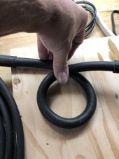
If you are that worried about it go diagonal and use 1/0 DLO cable, it is very flexible and has a minimum bend radius of 4x it’s diameter. This actually makes things go easier not having to assemble for top balance and reconfigure after.


As for compression it is a no brainer especially for a mobile application, the cells have a lot of mass and will want to move which would put more stress on the terminals than the minimal expansion of the cells when using springs.

The way I understand the damage from expansion and contraction is when the pouches expand and contract with no compression the pouch layers can separate, by using compression the pouches have a flat surface to push against when expanding keeping the pressure constant across the face of the cell.

On my EVE LF280N without compression they are rated 2500 cycles @1c with compression they are rated at 3500 cycles. That is not a small drop in performance. With the newer EVE LF280K they don’t even rate the cells without compression.
 

Attachments

  • 4847700E-43D6-40BA-BB38-58034D08638D.jpeg
    4847700E-43D6-40BA-BB38-58034D08638D.jpeg
    116.3 KB · Views: 85
  • 9864411F-8255-498D-845E-98F67574BB0F.jpeg
    9864411F-8255-498D-845E-98F67574BB0F.jpeg
    128.5 KB · Views: 87
If you are that worried about it go diagonal and use 1/0 DLO cable, it is very flexible and has a minimum bend radius of 4x it’s diameter. This actually makes things go easier not having to assemble for top balance and reconfigure after.


As for compression it is a no brainer especially for a mobile application, the cells have a lot of mass and will want to move which would put more stress on the terminals than the minimal expansion of the cells when using springs.

The way I understand the damage from expansion and contraction is when the pouches expand and contract with no compression the pouch layers can separate, by using compression the pouches have a flat surface to push against when expanding keeping the pressure constant across the face of the cell.

On my EVE LF280N without compression they are rated 2500 cycles @1c with compression they are rated at 3500 cycles. That is not a small drop in performance. With the newer EVE LF280K they don’t even rate the cells without compression.

Two questions, where the heck are you getting the DLO cable and what kind of diagonal jumpers are those?
 
I get the DLO cable from Skycraft surplus, the buss bar is Eriflex Flexibar and can be ordered in different amp ratings. I use a three layer 3/20/1 cut it to length and drill it.

Skycraft

Flexibar
 
Last edited:
ATM I’m going to use flexible laminated busbars to prevent the busbars loosening. That should prevent the bms from thinking the resistance of the cells is different than actual. Will also compress the cells to prevent them from delaminating, most likely without using springs. Unless someone can recommend a spring because I’m not intelligent enough to figure out what spring I need..
question about compressing with threaded rod, will all the cells have the same amount of compression applied to them? Is the difference negligible from the middle cell to the end cell?
 
Last edited:
If you are that worried about it go diagonal and use 1/0 DLO cable, it is very flexible and has a minimum bend radius of 4x it’s diameter. This actually makes things go easier not having to assemble for top balance and reconfigure after.


As for compression it is a no brainer especially for a mobile application, the cells have a lot of mass and will want to move which would put more stress on the terminals than the minimal expansion of the cells when using springs.

The way I understand the damage from expansion and contraction is when the pouches expand and contract with no compression the pouch layers can separate, by using compression the pouches have a flat surface to push against when expanding keeping the pressure constant across the face of the cell.

On my EVE LF280N without compression they are rated 2500 cycles @1c with compression they are rated at 3500 cycles. That is not a small drop in performance. With the newer EVE LF280K they don’t even rate the cells without compression.
Thanks for the info on the flexible busbars and cable!
 
ATM I’m going to use flexible laminated busbars to prevent the busbars loosening. That should prevent the bms from thinking the resistance of the cells is different than actual. Will also compress the cells to prevent them from delaminating, most likely without using springs. Unless someone can recommend a spring because I’m not intelligent enough to figure out what spring I need..
question about compressing with threaded rod, will all the cells have the same amount of compression applied to them? Is the difference negligible from the middle cell to the end cell?
I would use something like these. Four threaded rods and four of these valve springs are in the right ballpark for the EVE 280 cells, so if yours have similar requirements, the same should work well. The pressures within the pack should be similar.
 
mscdirect.com has an excellent selection of die spring. They give dimensions and force at a compressed dimension. I wouldn’t exceed 660lbs total or 165lbs for each of the 4 rods on a big cell. The trick is going to be coming up evenly. Triple check your numbers for your cells type. Don’t rely on my estimates. I use a single centralized die spring and did a load test and settled on 550lbs. Let us know about the laminated busses and if they keep needing re torquing every week or so.
 
mscdirect.com has an excellent selection of die spring. They give dimensions and force at a compressed dimension. I wouldn’t exceed 660lbs total or 165lbs for each of the 4 rods on a big cell. The trick is going to be coming up evenly. Triple check your numbers for your cells type. Don’t rely on my estimates. I use a single centralized die spring and did a load test and settled on 550lbs. Let us know about the laminated busses and if they keep needing re torquing every week or so.
I’ll check out mscdirect.
My understanding is the purpose for using the laminated flexible busbars is to prevent the re torquing. @cinergi uses them for that reason as he explained above. There has been complaints of the braided flexible busbars needing to be re torqued. And complaints the same for the solid busbars.
 
I wonder how many people feel this way after finding their cells bloated from a slight overcharge.
I wonder how many folks erroneously think that compression has any impact on the damage done by electrolyte decomposition that causes cell bloating.
 
Last edited:
I wonder how many folks erroneously think that compression has any impact on the damage done by electrolyte decomposition cell bloating.
Wouldn’t compression help to prevent cell bloating/delamination
 
Wouldn’t compression help to prevent cell bloating/delamination
Delamination yes, cell bloating no, at least within the constraints of bus bars not ripping battery terminals out because of bloating. On the flip side, bloating with compression will cause cell internal gas pressure to rise higher increasing the possibility of popping the overpressure vent port.

Cell bloating is the result of electrolyte decomposition, most often due to overcharging.

Electrolyte is called an organic compound, which is a politically and environmentally correct way of saying it is mostly hydrocarbon based, just like petroleum products.

Electrolyte decomposition breaks down to several chemical compounds. Several gases, mostly carbon dioxide and carbon monoxide, and hydro-carbon tars. It is the hydro-carbon tars that clogs up, primarily, the negative graphite electrode pores restricting lithium-ion migration through cell that does the real cell damage.

The bloating you see is just the gas pressure on the outside metal container. The actual cell lamination wrap is open at top to allow pos and neg foil terminals to escape the wrap. Gases within the wrap vent up through the open-ended wrap into the sealed metal container. The actual cell laminate wrap does not bloat.

Compression will help reduce delamination of negative electrode graphite from copper foil negative current collector and LFP positive electrode from aluminum foil. Delamination is most often causes by high cell currents with repeated heating and cooling cycles of the electrode material.

When the electrode material gets dried out due to extreme electrolyte loss it is also more prone to delamination, but the cell is pretty much toast by the time the electrolyte gets that depleted.
 
Last edited:
Delamination yes, cell bloating no, at least within the constraints of bus bars not ripping battery terminals out because of bloating. On the flip side, bloating with compression will cause cell internal gas pressure to rise higher increasing the possibility of popping the overpressure vent port.

Cell bloating is the result of electrolyte decomposition, most often due to overcharging.

Electrolyte is called an organic compound, which is a politically and environmentally correct way of saying it is mostly hydrocarbon based, just like petroleum products.

Electrolyte decomposition breaks down to several chemical compounds. Several gases, mostly carbon dioxide and carbon monoxide, and hydro-carbon tars. It is the hydro-carbon tars that clogs up, primarily, the negative graphite electrode pores restricting lithium-ion migration through cell that does the real cell damage.

The bloating you see is just the gas pressure on the outside metal container. The actual cell lamination wrap is open at top to allow pos and neg foil terminals to escape the wrap. Gases within the wrap vent up through the open-ended wrap into the sealed metal container. The actual cell laminate wrap does not bloat.

Compression will help reduce delamination of negative electrode graphite from copper foil negative current collector and LFP positive electrode from aluminum foil. Delamination is most often causes by high cell currents with repeated heating and cooling cycles of the electrode material.

When the electrode material gets dried out due to extreme electrolyte loss it is also more prone to delamination, but the cell is pretty much toast by the time the electrolyte gets that depleted.
Ok, so are you saying that compression helps nothing when the cells are used in a low power demand/slow charging solar setup? Since the cells won’t see high cell currents or repeated extreme heating/cooling cycles? Or is the regular heating/cooling cycles of a low power demand solar setup enough to warrant compression due to it possibly causing delamination. I’ve seen several posts of cells swelling from minor usage and not being overcharged when they are not compressed
 
The cells do expand/contract as a result of changes in SoC regardless of the C rate. In my case, I wanted to secure the cells for a mobile environment so that no matter the SoC, 300+/- kgf was being applied to keep them securely in place and in response to the EVE recommendations at the time about the recommended fixture. With 16 cells in a row, there's no fixed fixture that would maintain the cells in a tight configuration from 0% SoC to 100% SoC without exerting a ridiculous amount of force on the cells at 100% SoC.
 
Wouldn’t compression help to prevent cell bloating/delamination
Do you see any harm in putting 8 cells between two pieces of plywood, separated by some sort of padding, and then severed between four pieces of threaded rod?

Honestly, coming from a world of technical data, procedures, and quality assurance, a lot of what we do can be worded as “best practices” by some and “cowboying” by others.
 
The cells do expand/contract as a result of changes in SoC regardless of the C rate. In my case, I wanted to secure the cells for a mobile environment so that no matter the SoC, 300+/- kgf was being applied to keep them securely in place and in response to the EVE recommendations at the time about the recommended fixture. With 16 cells in a row, there's no fixed fixture that would maintain the cells in a tight configuration from 0% SoC to 100% SoC without exerting a ridiculous amount of force on the cells at 100% SoC.
The negative electrode graphite, which is about 20% of cell, expands by 9-11% of its volume between zero and 100% state of charge.

That amounts to less than 2 mm thickness change on a 280 AH cell. Barely noticeable.
 
Do you see any harm in putting 8 cells between two pieces of plywood, separated by some sort of padding, and then severed between four pieces of threaded rod?

Honestly, coming from a world of technical data, procedures, and quality assurance, a lot of what we do can be worded as “best practices” by some and “cowboying” by others.
To answer your question, not really. However as @cinergi and some others are saying, compression without flexible busbars can cause issues like busbar nuts/screws loosening or busbars sliding and or cell resistance/voltages being read incorrectly by the bms due to the loosening. Without flexible busbars it seems to me (from everything I’ve watched and read) that compression shouldn’t be used. Instead the snake pattern @Will Prowse is using or the space between cells that offgrid garage implemented should be done when solid busbars are used
 
Back
Top