diy solar

diy solar

Compress or not, flexible busbar or not

Compression is now apparently clarified in the datasheets, so it may be best to not cling to the information in older datasheets. They now mention a compression force range, which (for 230 Ah cells anyway) happens to equate to about 3kN (11.7 PSI) to 5kN (19.6 PSI). The implication is that this compression is the normal range of a cell taken from 30% SOC at 11.7 PSI to 100% SOC in a hard fixture (no springs or foam). Under normal conditions, the force should not exceed 7kN (27.5 PSI). It can exceed that if internal damage or cell leakage occurs.

In other words, when they said 11.7 to 18 PSI before, it seems they didn't mean don't let your compression exceed 18 PSI, they meant that if you clamp the thing rigidly the internal force will not exceed 18 PSI. This is what the new datasheet seems to say (well, now 19.6 PSI). It doesn't matter if they clamped one cell or one hundred in a stack. The force inside will be the same.

Well that’s not what I get out of the new data sheet.. it is for one cell not many compressed together.. if there’s more than one cell (8 or 16 or 19etc) then there’s more cells creating more expansion than what the data sheet is saying one cell is contributing.. therefore needing more room to expand than one cell. If room is not given for the cells to expand as in a rigid fixed structure then the cells (when multiple are put together, in my case 19) will have more pressure applied to them than one cell would in a fixed structure.. if one cell only expands .5mm then 19 cells want to expand 9.5mm therefore creating more pressure in a fixed rigid structure.. containing that expansion and preventing it with springs which are applying enough constant/similar force throughout the entire SOC also prevents over pressurizing/over compression of the cells.
Again a lot of premade packs (server rack) are not using springs and are instead using straps (which can stretch) and maybe the side of the case for compression. BUT they are (or should be) also using welded busbars or flexible busbars which prevent loosening of the busbars to prevent bms from reading the cells incorrectly and therefore balancing incorrectly.. A DIYed rigid fixed structure with or without foam should absolutely use flexible busbars. As long as there isn’t to much pressure/compression at high SOC and enough pressure at low SOC then it will most likely be fine.. but again who am I to say, I am learning as I go
 
Last edited:
Why 15mm expansion range? How many cells do you plan to stack in one box?


I used one 0.25" thick sheet per four cells. I built a 4S battery with one sheet, and four 8S batteries with two sheets each. The 8S batteries are combined as 16S2P. I built them as 8S because I can barely lift eight cells at a time, and I wanted to be able to lift each pack out of my containment box for any maintenance as needed. The packs allow the same braided bus bar to fit across the frames so that all bus bars are the same for the 16S batteries.

Here is a photo of two of the packs under top balance. You can see the foam at each end of each frame. Expansion of new cells from 30% to 100% SOC when charged at 0.1C or less was negligible.

View attachment 112514
The 15mm I talk of is the range of compression(tested by myself) that the springs would excert on the cells between approx 65% of the specified 300kgf ( this spec may be now superseded - seems the spec changes like the weather) up to 90% of 300kgf, cant say I've tested the spring compression/ rate beyond this point, but I'd say there would be a potential additional 10mm of compression left before getting anywhere near the upper specified kgf or psi limit.
My pack will consist of 8 or 9 cells (16 or 18 in two rows) and I'm happy for the range of expansion planned so far - hey may change over time, but I can easily add springs at the heady cost of £5 for six.
Obviously I'll keep an eye on expansion and from the compression testing records I've done I can easily gauge the pressure being excerted at any time.
 
New EVE specs for LF280K clearly indicate that the force exerted on the cell by the fixture at EOL (50KN or 11,000lbf) is much greater than BOL (3KN or 670lbf). They even show the fixture 6x M6 rods and 10mm thick end plates.
I've spent my entire career reading the tea leaves of data sheets of electrical components.
This one is pretty clear on conditions of use. No springs in sight, although the M6 will stretch a little at that load.
Do you HAVE to follow the datasheet test conditions? Absolutely not. Is it a good idea? Up to you.

View attachment 112352View attachment 112353

I believe all of the info in section 3 basically focuses on cell testing and failure modes. Basically this is what NOT to do! If you'd like to try to clamp the crap out of your cells and over-charge them, over-heat them, drop them, etc, feel free to follow all the recommendations in section 3... But I would not expect much longevity!

Anyone clamping their cells under this much pressure at a lower SoC in a rigid fixture as outlined above must have a screw loose, that or they're just hell-bent on pushing their cells to the limits of failure (literally!)
 
Well that’s not what I get out of the new data sheet.. it is for one cell not many compressed together.. if there’s more than one cell (8 or 16 or 19etc) then there’s more cells creating more expansion than what the data sheet is saying one cell is contributing.. therefore needing more room to expand than one cell. If room is not given for the cells to expand as in a rigid fixed structure then the cells (when multiple are put together, in my case 19) will have more pressure applied to them than one cell would in a fixed structure.. if one cell only expands .5mm then 19 cells want to expand 8mm therefore creating more pressure in a fixed rigid structure.. containing that expansion and preventing it with springs which are applying enough constant/similar force throughout the entire SOC also prevents over pressurizing/over compression of the cells.
Again a lot of premade packs (server rack) are not using springs and are instead using straps (which can stretch) and maybe the side of the case for compression. BUT they are (or should be) also using welded busbars or flexible busbars which prevent loosening of the busbars to prevent bms from reading the cells incorrectly and therefore balancing incorrectly.. A DIYed rigid fixed structure with or without foam should absolutely use flexible busbars. As long as there isn’t to much pressure/compression at high SOC and enough pressure at low SOC then it will most likely be fine.. but again who am I to say, I am learning as I go
One more time... more cells will not create more pressure. They all create the same amount of pressure. If they are constrained in a rigid case, they do not expand (they physically can't). What would be expansion is converted to pressure by the rigid end caps. The end caps and all of the cells have the same pressure. Allowing flexibility (e.g. springs or foam) is what allows expansion. That expansion is exchanged for additional pressure.

Zero pressure = lots of expansion
Springs or foam = limited expansion under pressure
Rigid case = no expansion under potentially higher pressure

The spec now says to put your cells in a rigid case under about 12 PSI pressure when they are at 30% SOC. They no longer say that higher pressure is bad, they simply tell you what to expect so that you can engineer your box correctly to keep it from blowing out. Remember that it is the expansion that is what needs to be constrained since expansion is caused by physical motion inside the jelly roll inside the cell, and motion is what leads to internal shorts. Internal shorts lead to reduced capacity.
 
I believe all of the info in section 3 basically focuses on cell testing and failure modes. Basically this is what NOT to do! If you'd like to try to clamp the crap out of your cells and over-charge them, over-heat them, drop them, etc, feel free to follow all the recommendations in section 3... But I would not expect much longevity!

Anyone clamping their cells under this much pressure at a lower SoC in a rigid fixture as outlined above must have a screw loose, that or they're just hell-bent on pushing their cells to the limits of failure (literally!)
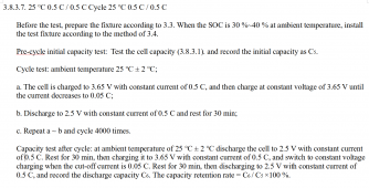
I thought maybe so as well until I read it a few times. However, they clearly state that they put the cell in a rigid fixture at ~12 PSI and then cycled at 0.5C charge/0.5C discharge 4,000 times at 25 degrees C. It is the basis test for the datasheet specification that cell capacity shall be at or above 80% of the original capacity. They also show the procedure to test 2,000 cycles at 45 degrees C. They further show the procedure to use if you want to stage your charging at 0.8C then 0.5C then 0.1C for rapid charging. They are telling us their recommended procedure to use to cycle our cells.

Note that their test cycles should take about 4.5 hours each (two hours charge, two hours discharge, half hour rest). 4,000 cycles takes 750 days to complete after the test begins. That is over two years. It is not surprising to me that they revised their datasheets after conducting long-term testing on batches of cells. They learned things that they had only speculated or thought were incorrect before they did the tests.

From the EVE LF230 datasheet (I reformatted it to remove the Chinese):

New_LF230_Cycle_Test.PNG
 
One more time... more cells will not create more pressure. They all create the same amount of pressure. If they are constrained in a rigid case, they do not expand (they physically can't). What would be expansion is converted to pressure by the rigid end caps. The end caps and all of the cells have the same pressure. Allowing flexibility (e.g. springs or foam) is what allows expansion. That expansion is exchanged for additional pressure.

Zero pressure = lots of expansion
Springs or foam = limited expansion under pressure
Rigid case = no expansion under potentially higher pressure

The spec now says to put your cells in a rigid case under about 12 PSI pressure when they are at 30% SOC. They no longer say that higher pressure is bad, they simply tell you what to expect so that you can engineer your box correctly to keep it from blowing out. Remember that it is the expansion that is what needs to be constrained since expansion is caused by physical motion inside the jelly roll inside the cell, and motion is what leads to internal shorts. Internal shorts lead to reduced capacity.

Honestly nobody is twisting your arm to comment so by all means cease to do so if you wish.. imo more cells do create more pressure/expansion. More pressure in a rigid/fixed case because the case doesn’t allow for expansion which creates more compression. If the cells “cannot expand in a rigid case” then there is to much pressure within that rigid case, exponentially more so the more cells in that rigid case.. with just one cell (like the data sheet) the amount of pressure in a rigid case is possibly ok because one cell only expands a minimal amount which wouldn’t create much pressure in a rigid case but it doesn’t say it’s ok to have that much pressure at high SOC for many years like our setups will be used for.. yes in a rigid/fixed structure the pressure on all cells is equal. All cells have a hard surface on all of their sides and no room for unequal pressure. If using foam on only the ends of the case one can argue that it’s not as rigid and I suppose that’s what your saying. However now the end cells do not have a hard surface on one of their sides and all the rest of the cells do have a hard surface on their sides. The softer foam on the ends now gives room for expansion which lessens pressure/compression compared to a completely rigid/fixed case. But that room is not between every cell when using foam only at the ends. So those end cells can have less compression on the sides against the foam. Which can also let those end cells bloat on the side against the foam and go unnoticed within the case. that wouldn’t happen if the end caps were rigid against the end cell without foam and instead springs used.. Also you say there is insignificant movement within your case and your foam thickness doesn’t change. That means that the expansion/pressure in your case is being turned into compression similar to what you say happens in a fixed/rigid case. Your saying it’s still not to much compression and maybe you are right, but springs would assure that it’s not to much compression..
If there’s 16 cells against each other and the .5mm to 2mm expansion of each cell is contained in a fixed rig that doesn’t allow for any expansion (other than allthread stretch) then all that proposed expansion is converted into more compression the more cells that are added. This is why foam or springs are used.. yes the springs or foam shouldn’t let the expansion simply happen, the expansion should be contained, but not by a rigid/fixed case that doesn’t allow for any expansion because that would put the cells under to much pressure. Could a rigid /fixed case withstand the pressure created by keeping 16 cells from expanding at all,, could the threaded rod and or all of the components hold up to that much pressure? Idk but I’d assume that would be to much pressure to put the cells under anyways, so why not use springs that can keep a more reliable constant compression with a hard surface on every side of every cell throughout the ENTIRE pack. Springs are enough to keep the cells compressed with very little expansion to prevent the over compression that can happen in a fixed/rigid case or a case that has “honestly no visible movement”. All the premade packs I seen allow for some expansion with just straps and use welded busbars or flexible if they are smart due to the expansion and how that can loosen busbars and cause bms issues. To stop all expansion with many cells together, imo is having to much compression
 
Last edited:
They are telling us their recommended procedure to use to cycle our cells.

They are telling us their recommended procedure as to how they cycled ONE of their cells... not many cells put together.
And that’s the entire point of this thread to compress or not, flexible busbars or not, that’s not for one cell but for many cells put into packs like we need. I will say it again, the poron foam is definitely an option and will most likely be fine for our home battery packs. Is it the best option, I’d say no, that springs are better but that is simply my opinion :)
 
Last edited:
If one cell takes Eve 2yrs to test to the extremes of failure( failure hardly the correct word for 80% capacity remaining), I feel most DIY builds will hit calendar aging first, as most DIY builders will never charge to 3.65v / discharge to 2.5v every day / week / month, let alone every 4.5hrs.
By the time rigid / spring / foam compression helps, we will be looking at lifepo4 with nostalgia, as the next generation or more energy storage technologies will make our todays top tech museum pieces.
 
Yes just like @Will Prowse and Offgridgarage say in their videos, calendar aging will most likely happen before any benefits of compression will be seen. However maybe not compressing the cells could possibly cause other issues in a nearer future than anticipated. And WTH why not, it doesn’t take much money (and I’m Cheap) to compress them with springs and it’s imo fun
 
The 15mm I talk of is the range of compression(tested by myself) that the springs would excert on the cells between approx 65% of the specified 300kgf ( this spec may be now superseded - seems the spec changes like the weather) up to 90% of 300kgf, cant say I've tested the spring compression/ rate beyond this point, but I'd say there would be a potential additional 10mm of compression left before getting anywhere near the upper specified kgf or psi limit.
My pack will consist of 8 or 9 cells (16 or 18 in two rows) and I'm happy for the range of expansion planned so far - hey may change over time, but I can easily add springs at the heady cost of £5 for six.
Obviously I'll keep an eye on expansion and from the compression testing records I've done I can easily gauge the pressure being excerted at any time.
And adjust if needed.
 
I agree calendar ageing will be the biggest issue affecting cell life, especially given my conservative use case. My main reason for fixed compression was I did not want to stress cell terminals with my 3P16S configuration with ¼ inch thick bus bars with 6 holes.
 
Well that’s not what I get out of the new data sheet.. it is for one cell not many compressed together.. if there’s more than one cell (8 or 16 or 19etc) then there’s more cells creating more expansion than what the data sheet is saying one cell is contributing.. therefore needing more room to expand than one cell. If room is not given for the cells to expand as in a rigid fixed structure then the cells (when multiple are put together, in my case 19) will have more pressure applied to them than one cell would in a fixed structure.. if one cell only expands .5mm then 19 cells want to expand 8mm therefore creating more pressure in a fixed rigid structure.. containing that expansion and preventing it with springs which are applying enough constant/similar force throughout the entire SOC also prevents over pressurizing/over compression of the cells.
Again a lot of premade packs (server rack) are not using springs and are instead using straps (which can stretch) and maybe the side of the case for compression. BUT they are (or should be) also using welded busbars or flexible busbars which prevent loosening of the busbars to prevent bms from reading the cells incorrectly and therefore balancing incorrectly.. A DIYed rigid fixed structure with or without foam should absolutely use flexible busbars. As long as there isn’t to much pressure/compression at high SOC and enough pressure at low SOC then it will most likely be fine.. but again who am I to say, I am learning as I go

The logic you are using is flawed.

If 1 cell is ok to stick in a fixed restraint, then you can stick 100 in the same fixed restraint and it will result in the same outcome.

Yes, 19 cells will result in 19 X more linear expansion than 1 cell would. There is also 19 X more rod between the end plates resisting the expansion.
It is a linear relationship and the resulting force that 1 cell would see in a fixed jig will be exactly the same as 19 cells in a fixed jig.

You also keep talking about using welded busbars as a solution but while that does solve the whole fastener loosening issue it still results in massive stresses on the terminals. Welded busbars are only a good solution if the terminals between cells have absolutely no relative movement, which will never happen if the cells are in contact with and acting upon each other.
Yes it takes the same amount of psi to keep 16 cells compressed or 1 cell compressed if that compression could vary thru the SOC.. However when those 16 cells try to expand in a fixed case there would be a possibility for 16 times the amount of room that isn’t available due to the fixed case which would increase the pressure/compression within the fixed case more than the pressure seen in a fixed case with only one cell, or am I wrong?
I wouldn’t think the all thread stretches anywhere near enough to keep the pressure from rising. I think the pressure/compression would simply rise and maybe not enough to matter but with springs that significant rise in pressure/compression that’s not needed could be lessened. The springs allowing enough compression to prevent swelling but not to much to allow the compression to rise more than needed at high SOC
 
You also keep talking about using welded busbars as a solution but while that does solve the whole fastener loosening issue it still results in massive stresses on the terminals. Welded busbars are only a good solution if the terminals between cells have absolutely no relative movement, which will never happen if the cells are in contact with and acting upon each other.

I’d have to disagree with welded busbars causing massive stress on the terminals. The terminals can flex the amount needed. Never have heard of anyone’s terminals breaking or issues because of it.. unless the cells were over charged but in that case there’s other issues. Look it up the better made newer premade packs use welded busbars. BYD SOC etc
 
If the cells “cannot expand in a rigid case” then there is to much pressure within that rigid case, exponentially more so the more cells in that rigid case.
You made this up with no basis in fact. EVE actually tested the pressures and reported them in their datasheet.

If using foam on only the ends of the case one can argue that it’s not as rigid and I suppose that’s what your saying. However now the end cells do not have a hard surface on one of their sides and all the rest of the cells do have a hard surface on their sides.
Using foam is no different than using springs. The foam exerts 300kgf uniformly across the face of the cells just like springs outside of a movable plate do. The pressure is the same. One difference is that springs increase the force with compression distance, but the foam is engineered to keep the pressure constant over a range of compression distances. In other words, the foam holds a constant 12PSI over a portion of the expansion range, while springs only have 12PSI at one distance.

The great advantage I see to rigid compression is that the cells cannot move in any appreciable way. This means that your busbar issues will go away since they will no longer move and cause trouble.
 
I agree calendar ageing will be the biggest issue affecting cell life, especially given my conservative use case. My main reason for fixed compression was I did not want to stress cell terminals with my 3P16S configuration with ¼ inch thick bus bars with 6 holes.
The thing about calendar aging is that the early data is extrapolated from limited testing. This testing is either actual calendar aging over months and extrapolated into years and/or "artificial" aging where they may play games with heat and charge profiles. In either case, true long term aging data takes a very long time to collect. The companies who make cells will quit bothering with testing this technology as the improve their cells, so long-term data will generally come from the field.

I'm hoping to see well over 15 years of life out of my cells, but that is just hope. Doing what the manufacturer recommends (compression, controlling temperature, etc.) is the best way I know of to maximize the life of my cells.
 
Just for kicks, let's look at the amount a 1/4" stainless rod will stretch when six of them are used to hold EVE 230 Ah cells. The datasheet from EVE says that the maximum pressure should be 15kN if the cells rupture. I'm doing math in public here, but that should come out to about 3,300 pounds of force. A stainless rod should have a Young's Modulus of about 140 gigaPascals, or roughly 20,300,000 PSI. If we calculate the stress on one rod, we should be able to divide later by the number of rods to see how much each rod will expand. Here we go....

Stress = Force/Area = 3,300 lbf / 0.049 in2 (for a 1/4" rod) = 67,227 PSI
Strain = Stress/Young's Modulus = 67,227 PSI / 20,300,000 PSI = 0.003 inches per inch of rod

If we assume that we have 8 EVE 230 Ah cells in a case, we'll need about 17" of rods to cover the length.

Now, 17 inches * 0.003 inches per inch = 0.056 inches.
If we use six rods, that would be 0.056/6 = 0.0094", or about 0.24mm.
The relative motion of each of the eight cells would be 0.0094" / 8 = 0.0011", or just under 29 micrometers.

That's if the cells rupture. Normal use would see much less motion.
 
I think my terminal tops with solid copper bus bars can tolerate that. I used six 1/4 steel thread rods.
Carbon steel will move less than stainless steel.

My issue with threaded rods is that it is very difficult to know how much force you have applied initially. Compressing the stack together with a known force and then finger tightening the nuts should work well. Like I mentioned before, my experience in compressing my stacks showed me that Irwin Quick-Grip clamps can apply just about 660 pounds when you squeeze them as hard as you can (I do have a fairly strong grip).
 
Back
Top