CalemChiara
New Member
- Joined
- Oct 6, 2022
- Messages
- 2
Hello, I thought I’d make a post to get some help if possible.
I am new to solar and am designing a 12v system for my campervan. I plan to use the system mainly to charge my phone, iPad, juicer, and most importantly my ebike battery, which is about 1000w total, so that’s why i have a large lithium battery.
My specs so far are:
- 2 solar panels (1x160w, 1x350w), wired in parallel. About 30amps total i think.
- 40a renogy rover mppt charge controller
-1500w/3000w pure sine wave inverter
- 300ah LiFePO4 12v battery
So I am watching Will’s classic 400w 12v solar tutorial and have some questions.
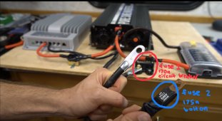
In his video, he has a main fuse which is a 170amp circuit breaker, connected to his fuse block and inverter, and then he also has a bolt on 170amp fuse on his battery cord.

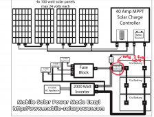
But in his diagram, he only has 1 main fuse, which I’m guessing is a a bolt on fuse to the battery?

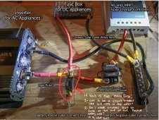
So, I am trying to get my head around this. So taking this image below as an example, my questions are:
1) for the ‘main fuse’, can it be a circuit breaker like the one in the first image in the red circle? (Assuming it’s the proper size for the amperage)
2) Do I need a second fuse on the positive battery cable? Say a bolt on fuse, like the one he uses in the first image in the blue circle? And if so, why do i need 2 big fuses? And what size would this fuse need to be? I thought one was enough for the invertor, does the battery need its own fuse?
3) Last noob question haha, can i copy the setup below, but instead of using a bus bar, just put all the negative leads on the negative battery pole, and skip the negative battery cable he says to connect to the bus bar?

So yeah, that’s it really. I can’t seem to figure out why he has 2 big main fuses (one on the battery cord, and one bolted on the wood), especially when the diagram only has 1 big main fuse and 1 for the charge controller. Does it have something to do with using a lithium battery instead of agm, since they can start bigger fires and need more protection?
And I’d rather not use a bus bar, so was just wondering if that is more for convenience and managing wires when the battery might get a bit crammed.
If you read this far, thank you so much! I‘m a total noob with this stuff so thank you so so much for your time and any help you provide!
Thanks
I am new to solar and am designing a 12v system for my campervan. I plan to use the system mainly to charge my phone, iPad, juicer, and most importantly my ebike battery, which is about 1000w total, so that’s why i have a large lithium battery.
My specs so far are:
- 2 solar panels (1x160w, 1x350w), wired in parallel. About 30amps total i think.
- 40a renogy rover mppt charge controller
-1500w/3000w pure sine wave inverter
- 300ah LiFePO4 12v battery
So I am watching Will’s classic 400w 12v solar tutorial and have some questions.
In his video, he has a main fuse which is a 170amp circuit breaker, connected to his fuse block and inverter, and then he also has a bolt on 170amp fuse on his battery cord.

But in his diagram, he only has 1 main fuse, which I’m guessing is a a bolt on fuse to the battery?

So, I am trying to get my head around this. So taking this image below as an example, my questions are:
1) for the ‘main fuse’, can it be a circuit breaker like the one in the first image in the red circle? (Assuming it’s the proper size for the amperage)
2) Do I need a second fuse on the positive battery cable? Say a bolt on fuse, like the one he uses in the first image in the blue circle? And if so, why do i need 2 big fuses? And what size would this fuse need to be? I thought one was enough for the invertor, does the battery need its own fuse?
3) Last noob question haha, can i copy the setup below, but instead of using a bus bar, just put all the negative leads on the negative battery pole, and skip the negative battery cable he says to connect to the bus bar?

So yeah, that’s it really. I can’t seem to figure out why he has 2 big main fuses (one on the battery cord, and one bolted on the wood), especially when the diagram only has 1 big main fuse and 1 for the charge controller. Does it have something to do with using a lithium battery instead of agm, since they can start bigger fires and need more protection?
And I’d rather not use a bus bar, so was just wondering if that is more for convenience and managing wires when the battery might get a bit crammed.
If you read this far, thank you so much! I‘m a total noob with this stuff so thank you so so much for your time and any help you provide!
Thanks


