diy solar

diy solar

Connecting Jackery 1500/2000 into Distribution Panel

macheung

New Member
Joined
May 31, 2021
Messages
108
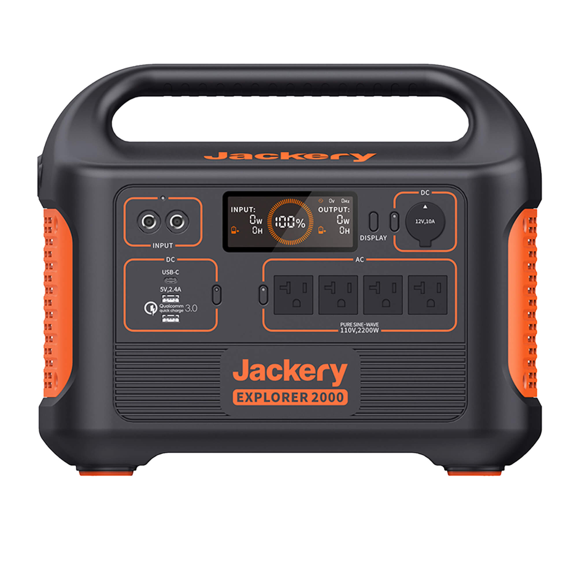
Have anyone ever connected the AC output of their Jackery explorer 1500/2000 through a generator input plug and breaker into their distribution panel? It can provide 1800/2200 watt of power which makes it handy to run a a fridge, some LED lights, and the furnace at once rather than running extension cords everywhere (and pulling the fridge out). Here is what I am thinking...
  1. Get a 20A 240V breaker (call it the Jackery breaker)
  2. Wire Jackery breaker into a generator socket
  3. Use a physical interlock device to ensure that the distribution panel's main grid breaker is off before the jackery breaker can be turned on.
  4. Make a wire where one end is a 5-20 (goes to Jackery AC out) and the other is matching generator plug. Wire the HOT of the AC output to both the +/- of the generator plug, so both rails would be powered at 120V. This would make any 240V circuits useless, but that's OK. NEUTRAL and GROUND would be wired as normal.
The only concern I have here is that in my distribution panel, the Neutral and Ground are connected. I've heard that some inverter have issues with that and want to see if it is OK with Jackery.
 
I was able to rig up a test extension where the ground and neutral are shorted together. When that, I measure 110V between Neutral to Ground. Tying the ground and neutral together is not a problem on the Jackery 1500
 
I confirmed that I was able to do this.

As a test (won't be setup like this on a permanent basis), I disconnected the panel from the grid and turned off all the beakers. Then I connected a 14/3 extension cord into a regular 14/3 wire and connected that to a 15A double pole breaker (let's call that the backfeed breaker). Neutral and Ground to their bars respectively, and wired the HOT to one of the HOT, and connected the two HOTs of the double pole breaker together using a 14 gauge jumper wire.

After confirming all breakers are off and measuring no voltage in both buses, I turned on the backfeed breaker and the Jackery AC output. Both bus in the breaker are confirmed to be powered up at 110V, and the Neutral and Ground are tied. Nothing is on. I was able to turn on any distribution breaker on at a time and draw power from the Jackery AC. This whole time, the panel's main breaker is off.

So one can in theory wire up a generator input and with the right adapter use the Jackery to send power to distribution panel. Though of course the 1.5kWh battery won't last very long, but may be able to power a couple of fridges overnight. Very handy if if it is hard to move your fridge to plug it into the Jackery directly.
 
Last edited:
Ok it works. I wired it in using a backfeed breaker 20A dual pole, where the breaker has a jumper that shorts the two hot rails together. My house pulls 600-800W on the important circuits (lights, fridge, sump pump, communication etc…). So this would only last maybe 1.5-2hr max. Next step, finding a way to charge this using solar during the day and my EV during the night.
 
Good you did that with the two hots wired together. That avoids brownout condition that can occur driving just one 120V leg (if a 240V load is switched on, carrying current through it to other 120V leg).
This should be fine for sources up to 20A. Above that, there would be an issue of > 20A going through shared neutrals, if present.

If you use an interlocked backfeed breaker and a 4-wire 120/240V input plug NOT wired together, it could be used either with a 120/240V generator or with your Jackery (using a suitably wired cord joining the two poles.)

"The built-in MPPT controller empowers the solar panels to operate at their maximum potential. It enables the Explorer 2000 to be recharged to 80% by 4*SolarSaga 200W solar panels within 2.5 hours."

Looks like both AC and DC inputs are slower than 1.5 - 2 hours, so your average draw needs to be lower.


Fridge should be about 1500 Wh/day, maybe 70W average. Have to look into the others, see what can be cut.
 
Above that, there would be an issue of > 20A going through shared neutrals, if present
Can you elaborate more on that? My Jackery can't supply more than 20A, but am interested to know why there would be a problem if one routes say 30A through a input breaker where the breaker shorts the 2 hot rails together when on. This is assuming the neutral wire from the battery/inverter would be sized to handle the amps. Note that I am not running any 240V appliance and all of the 240V double pole breakers will be off.

So for my Jackery 1500A unit (A since the current version is B which is different), I can charge it around 500W using either the 2 x AC adapter or solar panels. I have a grid tie SolarEdge setup where the optimizers shut down when grid is down but I wired a few panels separately in a Y branch down so I can connect it to this unit manually when grid is off. So that will give me around 500W of input during the day. At night, my plan is to connect this to my EV, which has a large battery. EV's HV DC battery -> EV 12V DC battery -> 1000W AC inverter -> AC charger -> DC Jackery battery. I know there is probably ~40% loss here, but given the size of the EV battery (90kWh), it is OK.

If I "live as normal" the house would consume like 800w average (without AC, dryer, cooker), which is too high for my 500W max charge rate. However, if I ration my electricity use, then I can probably get it below 500w average, though peak will still be 1500W range.
 
Can you elaborate more on that? My Jackery can't supply more than 20A, but am interested to know why there would be a problem if one routes say 30A through a input breaker where the breaker shorts the 2 hot rails together when on.

Some house wiring uses 3 + ground Romex. Two hots Red and Black, neutral White, bare ground.
With Red and Black each 120Vrms and 180 degrees out of phase from each other, if they happen to carry same current it just goes from one hot to the other. If not same current, the imbalance goes through neutral, so always |current(White)| = |current(Red)| - |current(Black)|

If Red and Black are wired in parallel, then white carries current = Red + Black. Your 30A source might supply 20A to Red, 10A to Black, and White carries 30A.

Putting the source through a single 20A breaker before going to both poles of a 2 pole backfeed breaker would be one solution.
Having a 120/240V split phase source or auto-transformer is another.
Powering just one phase of the panel, and turning off any breakers feeding 240V loads, is another.

If you examine your panel wiring and determine that every hot wire has its own neutral, then no problem. A 3 + ground cable wired to two independent single-pole breakers would be a problem. If 3 + ground only goes to a 2-pole breaker it would seem to be OK, but that depends on what it actually powers.
 
My grid feed is red black white. Though when my backfeed is in operation, the grid is disconnected physically from the panel. So I am connecting the +110vrms of the inverter to both of the red and black rails, neutral and ground to their respective bus. At this point both the red and black rail on the breaker is shorted together at 110vrms. All other double pole 240v are off as they would never work, any other single pole breaker should see 110v no matter if they are connected to red or black bus originally.
 
But do you have any cables (typically Romex) going from panel into the house wall, where a white wire goes to the neutral busbar, red wire goes to a 1-pole breaker, and black wire goes to a 1-pole breaker? Such wiring is OK only if red and black are fed by two different phases.

If red and black wires of a branch circuit are fed by same phase (e.g. both poles of a 2-pole generator/inverter backfeed breaker tied together), and more than 20A is available, that would be a problem.
 
My 200A main panel is fed from the grid with red/black/white. The branch circuits are either single pole, where it connects to neutral / ground / one of the bus (either red/black); or double pole red, black, white, ground.

When the backfeed is active, the panel is disconnected from the grid. All double pole branch circuits are also disabled with their breaker off. So only thing that is being powered by the backfeed is single pole circuits that links to only one of red or black (which are now tied together) through the backfeed breaker when it is on.
 
But do you have any cables (typically Romex) going from panel into the house wall, where a white wire goes to the neutral busbar, red wire goes to a 1-pole breaker, and black wire goes to a 1-pole breaker? Such wiring is OK only if red and black are fed by two different phases.

If red and black wires of a branch circuit are fed by same phase (e.g. both poles of a 2-pole generator/inverter backfeed breaker tied together), and more than 20A is available, that would be a problem.
I am doing the exact thing, so Hedges I want to understand your concern. We are shorting both sides of the panel together, so there can be no separate phases. All the 240V breakers are off.

The Jackery should internally limit the overall current draw to 15 amp, however I do not see a breaker in the website description. Assume it will shutdown with excessive loading.

Macheng I would remove the jumper from the 2-pole breaker, and instead use two separate cables that run to the Jackery plugs where it internally shorts both sides of the panel together.

The panel breaker is sized to protect the external wiring. The Jackery plugs appear to be rated 15 amps each, so would change to a 15 amp 2-pole breaker. In theory the jumpered 20 amp breaker could allow 40 amp current on a single plug. Two separate cables reduces the loading on a plug.

If I am creating a hazardous situation here someone please flame me for my protection.
 
With about 15A from Jackery, you'll never have the problem of > 20A in neutral wire of a branch circuit.
If using a source able to deliver more than 20A (e.g. 3000W or greater 120V inverter or generator), then depending on branch circuit wiring it could be a problem.

The problem isn't wires from inverter/generator to backfed breaker. It is existing house wiring. Only if one cable red/black/white connects two separate single-pole breakers to two separate branch circuit. Their current is returned in a single white wire. That's perfect if red and black are 180 degrees out of phase (120/240V split phase.) But not if red and black are wired together.
 
Under what situation would things be wired like that?

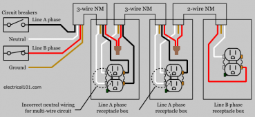
I've seen it a lot in house wiring. Saves cost, since 3+ground Romex can wire two circuits, instead of two separate runs of 2+ground Romex.

Just look inside your breaker box for any cables having red wire and see if they are used this way.


Diagram shows these separate circuits.

What it calls "incorrect wiring of neutral" is functional, but has the problem that opening neutral puts the two circuits in series. New code apparently wants a wire nut connecting the wires, with a stub to the outlet.
 
I've seen it a lot in house wiring. Saves cost, since 3+ground Romex can wire two circuits, instead of two separate runs of 2+ground Romex.

Just look inside your breaker box for any cables having red wire and see if they are used this way.
Ah I got it. It is a short cut. No, I don't have anything like that. All my 110V circuits are their own 2+ground Romex. My 240v circuits are 3+ground, but those are not involved in this setup. Should be good.
Macheng I would remove the jumper from the 2-pole breaker, and instead use two separate cables that run to the Jackery plugs where it internally shorts both sides of the panel together.
Yes, that would prevent the wire from overloading and allow the breaker to protect the wire more effectively. In this case however, the Jackery will cut out before the wire hit the limit as it can only deliver 15A max and I am using a 12G wire rated for 20A. I do agree it would be better though.
 
I've seen it a lot in house wiring. Saves cost, since 3+ground Romex can wire two circuits, instead of two separate runs of 2+ground Romex.

Just look inside your breaker box for any cables having red wire and see if they are used this way.


Diagram shows these separate circuits.

What it calls "incorrect wiring of neutral" is functional, but has the problem that opening neutral puts the two circuits in series. New code apparently wants a wire nut connecting the wires, with a stub to the outlet.
OK now I need a drink. Have never envisioned this before. With the circuit shown, assuming both hot out-of-phases are loaded equally, there would be zero amps measured on the neutral wire?

multi-current-romex-wiring-diagram-from-electrical-panel-3.png
 
OK now I need a drink. Have never envisioned this before. With the circuit shown, assuming both hot out-of-phases are loaded equally, there would be zero amps measured on the neutral wire?

View attachment 61506

Exactly.
Kirchoff's Current Law. "Sum of currents entering a node equals zero"


At any instant in time, sum of currents in red, black, and white wires will be zero.
If current in red and black are equal but opposite, then zero current in white.

An exception would be a capacitor. Current flows in but none flows out. Instead, E-field grows across the dielectric. So "Displacement Current" is invented to say that Kirchoff is correct.
 
~40 years ago graduated with a mechanical degree. Then started taking electrical courses for a complementary electrical degree.

Took my first AC/DC circuitry fundamentals. Aced the DC section without even studying, it just came natural. I totally understand Kirchoff's Law in DC circuits.

Then got to the AC section and flunked despite how hard I studied. Amps leads/lags current in inductive/resistive @#$%*&^#^. Could not (and still cannot) grasp. Will have to study exactly how the neutral phases cancel out.
 
Springs and weights. Those are capacitors and inductors, respectively.

Just ignore AC. Analyze the branch circuit as if powered by +120VDC/-120VDC. Then compare to +120VDC & +120VDC on the red and black. With a 6 ohm load from black to white, and a 6 ohm load from red to white.

I got pretty far regarding MOSFETs as a hose being pinched, plus ohms law. Designed part of state of the art microprocessors for HP that way.
Bipolar was harder to understand. I finally had a decent understand from grad school (some people get it in undergrad, but I dropped that class rather than flunking it, and was part CS so EE Lite.)

More advanced classes addressed quantum tunneling without crossing over an energy barrier. I dutifully plugged numbers into equations and got A's in my classes, but that doesn't mean I understand it.

I am messing with inductors and the like for my job, RF resonators, common-mode chokes, and so on. I manage to take bench measurements, but getting simulations to run can be harder.
 
Then got to the AC section and flunked despite how hard I studied. Amps leads/lags current in inductive/resistive @#$%*&^#^. Could not (and still cannot) grasp. Will have to study exactly how the neutral phases cancel out.

Close breaker between battery bank and inverter's capacitors. There is an inrush of current, possibly enough to blow the fuse. A 50V battery connected to capacitor is briefly pulled down toward zero volts and massive current thousands of amps rushes through. As capacitor charges, voltage rises and current tapers off toward zero.

That's current leading voltage. Closing the switch was a rise in voltage, like AC. Just a square wave rather than sine wave.
Same leading current occurs with sine wave AC voltage, but it is a nice smooth sine wave current.

Xc = 1/(j 2 pi f C) = -j/(2 pi f C)
"-j" is 90 degrees phase shift one way.

Xl = j 2 pi f L
"j" is 90 degrees phase shift the other way.

R doesn't have a "j", no phase shift.

You can add R in series with Xc or Xl like they are at right angles, orthogonal.
| R^2 + Xl^2| gives magnitude of impedance, so you can calculate magnitude of current flow. A bit of trig and you get phase.

The math for dynamic mechanical circuits and AC circuits is identical. There is also damping (Q), and so forth, same for both.
Heat flow same as resistance.

I avoid using calculus if possible.
 
Back
Top