


You are using an out of date browser. It may not display this or other websites correctly.
You should upgrade or use an alternative browser.
You should upgrade or use an alternative browser.
Connecting Neutral & Ground from Generator to Home
- Thread starter ePowerBank
- Start date
RCinFLA
Solar Wizard
- Joined
- Jun 21, 2020
- Messages
- 3,563
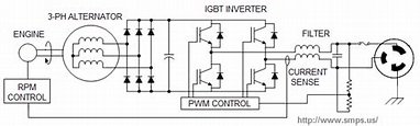
For an inverter-generator, a three phase permanent magnet alternator just goes to a full wave rectifier to make high voltage DC. The inverter module takes the HV DC and PWM chops the HV DC with an H-bridge MOSFET arrangement just like a normal HF inverter. A final L-C filters the PWM to sinewave, again just like a regular HF inverter. The inverter module has its own frequency standard that determines the PWM chopping frequency and resultant 60 Hz output. The output frequency has nothing to do with alternator/engine speed.
A permanent magnet alternator output voltage and current depends on its load and its rpm. With ECO turned off, and full engine rpm (about 3800 rpm) on a 120vac model inverter-generator, the PMA rectified output ranges from about 180vdc to 300vdc, depending on AC load. It must maintain some overhead above 170 vdc to make the 169.7 Vpeak required for 120v rms AC output.
For ECO mode, the engine rpm's is reduced to maintain about 180 VDC on rectified alternator output. If a heavier load is put on generator the voltage will slump and the rpm's of engine is increased to raise the HV DC back up to 180 VDC to feed the PWM inverter. A sudden load will cause the inverter to clip AC output peaks due to HV DC slump until engine spins up to the required higher rpm to meet the new load. The 60 Hz output does not change since it is determined by inverter internal clocking. The feedback control can be done as output AC current sense, the results is same with the approximate 180 vdc being maintained.
Synchronization is just a matter of synchronized the two inverters. This is typically done by first generator started present 60 Hz to other generator's inverter output. The second generator must not yet have been started. When the second genertor is then started, its electronics in the inverter picks up the 60 Hz from first started generator and the second generator's inverter synchronizes its electronic inverter clock to the first generator. This puts the two inverters in synchronized AC output phasing.
Key is you cannot parallel two already running inverter-generators as if they are started up individually without parallel connection they will be operating at independent phasing. If you then connect parallel kit wiring it can be like a short circuit depending on how far apart the two generators phasing is.
I have never seen an inverter-generator that parallels the two HV DC output. It would be too dangerous. It would likely also screw up the individual feedback control unless the current from each PMA is compared to avoid one from taking more of the load. That would require extra interconnect wiring to report the PMA current between each generator.
There are many Youtube videos out there that say don't waste your money on an expensive parallel kits sold by manufacturer, just make a 'Y' suicide cord with two male plugs. Very irresponsible and unsafe but it does work. All the plastic shrouded banana plugs on a parallel cable kit go to the AC outlets in the inverter-generator. Many inverter-generator manuals have basic block schematics that show their connections.
Last edited:
I took apart a Honda generator that had been fried to find out what it did, It was destroyed by whatever the owner did to it, repair would have exceeded its value, it was scrapped, I never did get a complete manual but their cost for the inverter boards were selling for more than the generator was worth, that was a first generation Honda 3kw units, I havent touched one since but thanks for the complete fill in on a more advance unit than i have seen. I remember a toroid in there, but the unit was so burnt that it was hard to tell. He was backfeeding his house when the power came back and flipped the main before disconnecting the generator, the Honda did not survive, the igbt were blown up so bad it was impossible to figure out. I did understand that a separate clock must be involved as the variable speed and 60 hz do not work, this unit was not high enough voltage to be directly driven to the inverter. My trusty Onan always works, very old school
ePowerBank
New Member
- Joined
- Apr 13, 2021
- Messages
- 133
Thanks @Tecnodave. I feel enlightened.Exactly where did you discover this.......
In the ones that I have been into the generator is three phase AC variable frequency which is exactly what allows the generator to throttle up faster as more power is needed and reduce the throttle when less power is needed. This results in variable frequency at output of the generator, it varies from about 30 hz up to 400 hz, again three phase Then it is then rectified to DC. that is what appears ot the banana connectors......DC....The inverter in the generator takes this DC and inverts this into AC........The inverter in only one generator is used to provide the 60 hz. output
I have not torn into every inverter generator but the ones I have been into this is exactly how it was done.
I am way too curious on electricity to not dig into a variable speed generator that maintains constant 60 hz
Basic physics 3600 RPM 2 pole Generator ......60 hz...
Variable speed ......Variable frequency
It is not too hard to sync the inverters if both inverters are used but syncing two generators directly is not trivial, if one generator were to cough everything is knocked out of phase.....dead shorting each other out
Now you know how its done
Prove me wrong....
I think this helps explain why banana lead wires are such light gage.
Also, if I'm understanding correctly here, it seems that the inverter is best practice in joining (smoothing out) 2 devices, or inverters in this case.
I can't say I've seen very many parallel generator setups.
The theory of single inverter driving the output also is supported by fact that I'm able to directly connect to inverter control panel outlet, although it's only 30A. I wonder, however, if it should be the host inverter?
Taking this theory a step further, I wonder how the parallel wire kit is working with the NEMA 10-50R. I'd like to be connected at that point for the higher amp capacity, but not certain about the neutral path since that outlet is only 2 hot legs + 1 ground.
If only my case (#1 below) would have been designed something like #2 or #3 below from same company:
1 - 4500 (open frame) unit for some reason utilizes this OLD NEMA 10-50R (???)
2 - 7500W unit only uses banana leads while 50A outlet hooks directly from invertor (+++)
3 - 4500 unit parallel kit utilizes NEMA 14-50R, which includes NEUTRAL
Pose consumer dissonance :--(
My next step is to try hooking into my NEMA 10-50R with a ground fault tester.
I wonder if within my neutral topic is the topic of floating neutral (which I do have).
As I understand, if I have floating neutral, then the inverter needs to utilize my home panel ground system (Separately Derived System).
Thank you again !
ePowerBank
New Member
- Joined
- Apr 13, 2021
- Messages
- 133
WOW - very interesting! Not sure you caught I'm actually using the smaller 4500W Powerhorse(s) (p/n 83171). I wish the 83171 manual had instructions like this! I contacted Northerntool previously in absence of parallel connecting instructions (both the inverter and the parallel kit = nothing) - the verbal direction clearly was "start first, then connect". No pun, I was shocked and questioned him and he said all their training was just that...Read attached two pages from Powerhorse manual, highlighted text.
Everything I hear (as you previously advised) and read consistently (other brand manuals) has been otherwise, connect first then start. Anyone has otherwise I'm all ears - I think I checked at least 4 other brands. I actually tested (start 1st, connect 2nd) and didn't like the way it sounded plugging in the 2nd unit (no load) and hearing both syncing. The 7500W unit makes it very clear though. I think I'm going to post something in their public forum for my p/n in question of connecting instructions to hopefully get the careful correct answer...
Thanks for that detail!
ePowerBank
New Member
- Joined
- Apr 13, 2021
- Messages
- 133
I'm with you on the killer cords - I've seen those too and wouldn't want to risk 2 brand new inverters! CRAZYThere are many Youtube videos out there that say don't waste your money on an expensive parallel kits sold by manufacturer, just make a 'Y' suicide cord with two male plugs. Very irresponsible and unsafe but it does work. All the plastic shrouded banana plugs on a parallel cable kit go to the AC outlets in the inverter-generator. Many inverter-generator manuals have basic block schematics that show their connections.
Thanks for unpacking the iceberg on how the inverter basics - your experience is more than a book I think...
ePowerBank
New Member
- Joined
- Apr 13, 2021
- Messages
- 133
Exactly where did you discover this.......
In the ones that I have been into the generator is three phase AC variable frequency which is exactly what allows the generator to throttle up faster as more power is needed and reduce the throttle when less power is needed. This results in variable frequency at output of the generator, it varies from about 30 hz up to 400 hz, again three phase Then it is then rectified to DC. that is what appears ot the banana connectors......DC....The inverter in the generator takes this DC and inverts this into AC........The inverter in only one generator is used to provide the 60 hz. output
I'm still trying to understand how to translate neutral through my circuit (Inverter <--> House).
I've searched and can't find any Inverter Parallel kits that use "four" banana wires, not to mention a NEMA 10-50R (very old school plug).
I think I'm hung up on the banana leads being DC - or do I have this wrong?
When connecting the banana leads to Inverter control panel, I get continuity between:
Red/Black banana lead to Inverter L14-30 plug Leg1/Leg2
Green banana lead and Inverter L14-30 plug ground
White banana lead and Inverter L14-30 Common
These are all for AC, right?
ePowerBank
New Member
- Joined
- Apr 13, 2021
- Messages
- 133
A picture to go with above: Model# DPC-004 (from the website).

ePowerBank
New Member
- Joined
- Apr 13, 2021
- Messages
- 133
I'm told by supplier product is modified sine wave. Therefore, I assume I have High Frequency Modified Sine Wave in my case.
How that translates to AC I'm not quite sure, but wonder if it works like traditional AC we have in US, using neutral in transformer to pull out the 120v? I am able to to 120V from L1 or L2 to ground in the NEMA 10-50R, so it's not only 240V with the parallel kit.
Here's a pic of the inverter board. The 2 wires at opposite corners (black/red) lead to the L1/L2 of the L14-30 plug.
RCinFLA
Solar Wizard
- Joined
- Jun 21, 2020
- Messages
- 3,563
I have seen an inverter-generator that is modified sinewave but it is an old rare relick. Pretty safe to say all inverter-generators are sinewave output.
The banana plugs are AC and just go to the AC outlet socket internal to the inverter generator. The color coding is to ensure you don't reverse the leads and get the two inverter-generators running 180 degs out of phase. With the power being taken from the actual banana lead connections reversing them does not even matter as the paralleling of the AC output will also get matching reversal.
It is a slight bit better to keep the two gens in phase per the parallel color code as a half cycle surge current spike will be applied in exactly same way on both generators inverter circuitry. For a 240 vac inverter-generator their are two 120v inverters operating in series. One of them is master and one is slave for phasing so it is preferable to have any surge spike phasing to be applied to master or slave side on each inverter.
Surge spikes can pertubate the phase synchronization so it is preferred to have any pertubation caused by surge spike to react the same way on both generators.
Last edited:
RCinFLA
Solar Wizard
- Joined
- Jun 21, 2020
- Messages
- 3,563
If it was me, and you cannot get the blue box apart to replace socket with NEMA 14-50, then I would cut the two banana lead cables at the blue box and build a new box with a CR6369 or NEMA 14-50 socket.
If you want a bandaid, use the L1, L2 hot line from the blue box NEMA 10-50. Make another two cords going to your service entrance CR6369 or NEMA 14-50 female cord plug. One of the two cores to the blue box NEMA 10-50 for L1,L2. Second cord only connecting white neutral and green ground wires on service entry CR6369 or NEMA 14-50 female plug going to a NEMA L14-30 male plug only having neutral & ground connections that you plug into either generator L14-30 outlet.
In the bandaid, an unplugged-in male NEMA L14-30 plug neutral could have voltage if you have 120v house loads plugged in.
I don't like the band-aid, and as I said I would cut the cords to blue box and make a NEMA 14-50 socketed replacemet box.
Other possibility is you can probably find a third party parallel kit cord or other brand parallel kit cord with a proper four wire 50A socket.
Last edited:
ePowerBank
New Member
- Joined
- Apr 13, 2021
- Messages
- 133
Thank you for ideas. Seems basic case of dammed if I do or don't.... Good news is the parallel kit was only $40.
With generators taking 5 months to fill order (Feb - June) I'm not sure what wait is - especially with import line currently sitting in Pacific....
Seems we're aligned that it's OK (or desired) for neutral to pass through to parallel kit/gensets - as when connected to L14-30 (parallel mode).
Wonder what purpose is though - not for syncing, and apparently not to split the 240 like when using grid transformer.
I just realized a check/test I didn't try that helps prove/test neutral function - measure parallel NEMA 10-50R L1/L2 to "house" neutral and ground.
ePowerBank
New Member
- Joined
- Apr 13, 2021
- Messages
- 133

ePowerBank
New Member
- Joined
- Apr 13, 2021
- Messages
- 133
Just realized I need to patch the ground through too, sine I don't plan to physically connect cords 1 & 2, but isolate this neutral test.
Thank you again !

Thank you again !
ePowerBank
New Member
- Joined
- Apr 13, 2021
- Messages
- 133
NEMA 10-50R box opened (or is Pandora's box)

RCinFLA
Solar Wizard
- Joined
- Jun 21, 2020
- Messages
- 3,563
As configured, parallel kit outlet is only good for 240vac loads.
Manufacturer saved a couples of pennies not putting in NEMA 14-50 in parallel kit box.
One possible warning. Some inverters-generators do not allow neutral to ground bonding. Many 120vac only inverter-generators state this in their manual, usually stated as 'do not connect generator to house wiring'. I would find it unlikely for a 120/240 vac generator but anything is possible with a cheap chinese inverter-generator.
Cord #2 plugged directly into NEMA L14-30 on generator implies this generator should be able to be neutral grounded. Cord #1 adaptor to parallel kit does not bring neutral to house service entry box from parallel kit box so not very useful as only 240vac devices would be powered.
Worse than just having 240vac, any 120vac loads will have floating neutral so the 120vac house outlets will have varying voltage depending on how much 120vac loads are on each side of L1, L2 to neutral. Very unsafe and hazardous to 120 vac appliances plugged in. Very bad design! Shows total lack of understanding of U.S. split phase system. So can you believe the cord #2 plugged into one generator L14-30 outlet to house service entry is correct ???
You should contact Northern Tool and tell them they should remove this parallel kit from their product line as it is a dangerous product. At least get your money back.
If single gen is capable of being neutral ground bonding then the paralleled generators should also be neutral-ground bondable.
Last edited:
ePowerBank
New Member
- Joined
- Apr 13, 2021
- Messages
- 133
As configured, parallel kit outlet is only good for 240vac loads.
Exactly what I've been wondering.
Does it mean anything, however, if there's 120v L1/L2 to Ground on the NEMA 10-50R when both genset are on?
Is that what would happen if one of these old plugs was in our house?
ePowerBank
New Member
- Joined
- Apr 13, 2021
- Messages
- 133
One possible warning. Some inverters-generators do not allow neutral to ground bonding. Many 120vac only inverter-generators state this in their manual, usually stated as 'do not connect generator to house wiring'. I would find it unlikely for a 120/240 vac generator but anything is possible with a cheap chinese inverter-generator.
Appreciate concern! I hope this (not for house backup) doesn't apply for me.
In my case I actually don't want bonding at gensets, but at MAIN panel.
As I understand, gensets that have bonding at gensets are sold towards portable use, or for case of a large unit that OSHA wants grounded, AKA, Separately Derived System. I don't have continuity between ground and neutral on my generators, therefore, I assume I have Floating Neutral.
Also, manual suggests home backup is an option:

RCinFLA
Solar Wizard
- Joined
- Jun 21, 2020
- Messages
- 3,563
Only if neutral is grounded internal to generators. This would be a code violation with current flowing on ground wire of parallel kit box.Exactly what I've been wondering.
Does it mean anything, however, if there's 120v L1/L2 to Ground on the NEMA 10-50R when both genset are on?
Is that what would happen if one of these old plugs was in our house?
Voltage drop caused by 120vac loads across parallel kit cable would mean there can be some voltage difference between generator case ground and house grounding. Again, not a safe situation.
"Is that what would happen if one of these old plugs was in our house?"
NEMA 10-50 plugs are only used on some ranges, clothes driers, and maybe some window A/C's that only require 240vac.
Last edited:
Similar threads
- Replies
- 20
- Views
- 395
- Replies
- 84
- Views
- 4K
- Replies
- 0
- Views
- 322
- Replies
- 297
- Views
- 9K