diy solar

diy solar

Connecting Two Separate LiFePO4 Banks

Dhowman

San Diego, California
Joined
Dec 29, 2019
Messages
295
Location
San Diego
Hello -

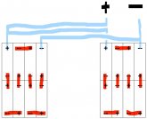
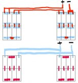
I'm in the final planning stage of a build out and have a couple of questions. Only way for me to fit the 16 180Ah CALB cells I'm planning for is in two boxes of 8 each on either side of my camper. It's a 24V, 360Ah system, but wondering if I need to be concerned about the side that's nearer to my loads (right side in pics below) taking a bigger hit than the one that's on the opposite side. My original plan was to simply arrange them in the first configuration below (2-12V/360Ah banks connected in series across the aisle), but wondering if connecting 2-24V/180Ah banks in parallel across the aisle might keep the 2 sides more evenly matched, even if that config would be a PITA for a BMS (16 cells to balance vs 8). Blue, below, are the parallel connections and Red are the series.
Parallel First Series First.JPG
Biggest load I can expect will be from a 1500W induction cook top (via Victron MultiPlus 24/3000/50) that I expect will draw about 15A [Edit: 70A] from my bank but not for long periods. With charging, I suppose they could see 30-40amps going in for extended periods (from 4 24V 300W panels or the MultiPlus). Maybe it's not a big deal as long as I size the wires running between the 2 banks adequately. They'll be about 4 feet long. Will likely run 2 pairs across for the first config so I can go w/ higher gauge (smaller wire) than for the bottom config. Any recommendations/suggestions?

And lastly, anyone have any good recommendations for a (free/online?) software tool to draw schematics? Would like to be able to insert pics of the components I'm using and then diagram the wiring between them. Tried both Word and Visio but both are tedious if you need to move something or rearrange things to make the wiring easier to conceptualize. Guess I'm spoiled after having figured out Google SketchUp for the 3D physical layout of everything. Couldn't imagine having figured all that out without it.

Thanks Folks!
 
Last edited:
The first solution, with a 12V pack on each side, wired in series, will take the load perfectly balanced.

The second solution with two 24V packs in parallel will load the right one a little heavier, due to the longer wires to the left hand pack.

Your 1500W cook top will draw about 70A from your pack.
 
@sajjen Yeah, sorry, inadvertently dropped a "0" from that amp figure for the stove. It's 150A for a 12V bank, but since I have a 24V bank, you're right, about 75A. (when set to high).

So the very slightly shorter round trip cable length in the series-connected banks is a bigger factor than the ability of the parallel-connected banks to self-balance the 2 sides? Maybe my BMS will do that anyway in the series-connected banks but was just wondering if it might be aided by having the two sides connected in parallel.
 
Last edited:
@sajjen Yeah, sorry, inadvertently dropped a "0" from that amp figure for the stove. It'll draw 150A w stove set to high.

How do you get 150A from a 1500W load on 24V?

So the very slightly shorter round trip cable length in the series-connected banks is a bigger factor than the ability of the parallel-connected banks to self-balance the 2 sides? Maybe my BMS will do that anyway in the series-connected banks but was just wondering if it might be aided by having the two sides connected in parallel.

You are not making any sense here.

Two 24V packs in parallel will go out of balance and will require two BMSs. It's a bad idea in almost all instances.

Having longer wires in the middle of a 24V pack is no different from having longer cables between the pack and the load. It can in no way lead to pack imbalance. All it does is losing a bit of energy to resistive heat in the cable.
 
Hello -

I'm in the final planning stage of a build out and have a couple of questions. Only way for me to fit the 16 180Ah CALB cells I'm planning for is in two boxes of 8 each on either side of my camper. It's a 24V, 360Ah system, but wondering if I need to be concerned about the side that's nearer to my loads (right side in pics below) taking a bigger hit than the one that's on the opposite side. My original plan was to simply arrange them in the first configuration below (2-12V/360Ah banks connected in series across the aisle), but wondering if connecting 2-24V/180Ah banks in parallel across the aisle might keep the 2 sides more evenly matched, even if that config would be a PITA for a BMS (16 cells to balance vs 8). Blue, below, are the parallel connections and Red are the series.
View attachment 4695
Biggest load I can expect will be from a 1500W induction cook top (via Victron MultiPlus 24/3000/50) that I expect will draw about 15A [Edit: 70A] from my bank but not for long periods. With charging, I suppose they could see 30-40amps going in for extended periods (from 4 24V 300W panels or the MultiPlus). Maybe it's not a big deal as long as I size the wires running between the 2 banks adequately. They'll be about 4 feet long. Will likely run 2 pairs across for the first config so I can go w/ higher gauge (smaller wire) than for the bottom config. Any recommendations/suggestions?

And lastly, anyone have any good recommendations for a (free/online?) software tool to draw schematics? Would like to be able to insert pics of the components I'm using and then diagram the wiring between them. Tried both Word and Visio but both are tedious if you need to move something or rearrange things to make the wiring easier to conceptualize. Guess I'm spoiled after having figured out Google SketchUp for the 3D physical layout of everything. Couldn't imagine having figured all that out without it.

Thanks Folks!
If the electronics are near the right battery bank is flip the arrangement to eliminate the positive crossover cable & use chassis ground for the negative.
 
I'm going to chuck this in here:
Have you considered using a BUS system ? Meaning using a (+) & (-) BUS Block. Attaching your batteries with equal length cable to the bus bars, then single cable from bus bars out.
 
If the electronics are near the right battery bank is flip the arrangement to eliminate the positive crossover cable & use chassis ground for the negative.
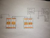
They are. You mean like this? 24V Camper and 12V Vehicle can share common ground? That would be nice but wondering what, if any, downsides there might be. Clearly I'm not an EE/Electrician, so these may be stupid q's but appreciate the patience and expertise of those of you who might be!
IMG_5835.JPG
I'm going to chuck this in here:
Have you considered using a BUS system ? Meaning using a (+) & (-) BUS Block. Attaching your batteries with equal length cable to the bus bars, then single cable from bus bars out.
I guess that's why I'm asking. I see folks recommend equal length leads from POS & NEG terminals all the time and, for me, that would mean coiling up a 4ft negative lead on the right side in the first configuration in my original post (to match length of the pos lead coming from the left).

If I understand reply from @sajjen above correctly, it doesn't matter and I can kinda see why.

Only remaining question, then, might be what gauge wire to use for the 4 ft cross-over that won't impede current more than the bus bars connecting the cell terminals do.

Again, apologies if I'm not making sense or just don't understand the physics involved.
 
Here is a link with some good info for wiring batteries if you haven't seen it already.

Great article! Can't tell you how many parallel-connected batteries I've seen using "Method 1" that in about 5 mins could be configured via "Method 2." While it addresses good/better/best for parallel connections, it doesn't really address the issue of whether 1st or 2nd config in my original post is best, except for maybe these two things:

1. Left side of the following pic is better than right ("In order to get a better balancing it is simply necessary to get the number of interconnecting links as close as equal between each battery and the final loads.")
IMG_5836.JPG
2. The 2nd config in my original post could be improved (per his Method 2: "It is simple to achieve but the difference in the results are truly astounding for such a simple modification.") IF my battery terminals were equidistant to my load/chg terminals, but they're not, so this recommendation doesn't make much sense for me cuz it would look like this:
Parallel First Series First-2.JPG

Either way, unless there are any other opinions out there regarding a better setup (e.g. @SCClockDr 's use of grounding to chassis that I hope I've diagrammed correctly in Post #8, above), think I'm going to go with the 1st config in original post. My BMS, hopefully, will keep everything nice and balanced across all 8 parallel connected cell pairs regardless of what side of the series-connected "cross over" they're on.
 
I'm using #3 in my setup.
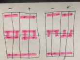
20200108_165907.jpg

Your not using a shunt for reading the batteries amps in/ out SoC?
 
I've never heard of a shunt being used on the Positive side, yes it can be done but never seen it, it presents safety issues and more. They traditionally go on the negative side, one per battery if measuring each batteries status, or one per "bank of batteries" to measure the overall bank health and status.

Helpful article: http://beamalarm.com/Documents/measuring_rv_battery_current_with_shunts.html
 
Shunts are usually placed on the negative side because that makes for cheaper electronics to measure the shunt. It is not a safety issue. The linked site has basic misunderstandings of electrical theory, not a source worthy of trust.

In a grounded system, having the shunt on the positive side has the great advantage that the negative bus will actually be at ground potential. With a negative side shunt, there will be a small voltage on the negative bus, based on the load of the system.
When I first read this, I thought your comment "linked site ... not a source worthy of trust" was referring to the BMS site I linked to a couple posts up and freaked out.o_O

Did some digging and found this by the BMS's maker, stating the same thing you are:

"The SBMS is designed as common negative that is why the external current shunt needs to be on the positive side. Is more expensive and complex to have common negative that is why most others have common positive and so current measurement is done on the negative line."

It was only then that I realized you were referring to the beamalarm.com article, not my BMS source. Whew!

Thanks folks, but almost had a heart attack given that the only way I can make this setup work financially is with a DIY battery bank but decent BMS's for this purpose seem practically non-existent and it took me a good long time to find this one and follow some folks who are using it in RL.
 
The Electrodacus BMS looks like one heck of a piece of kit and I've pointed people at the product line as it fits with many uses and capabilities are quite good especially for the price point. If they recommend specific pieces then use what they recommend or an exact equivalent in specs.

Refer to their docs & methods and ask them question if in any doubt, they know their product, it's design & what works best for their setup. I've had people tell me how to do things or I have done things wrongly BUT I default to the Manufacturer and their design & recommendations as THEY know what their products do, how & why. Not always easily if dealing with imported stuff with terrible docs (poor translations being just one issue), if any docs at all.
 
The Electrodacus BMS looks like one heck of a piece of kit and I've pointed people at the product line as it fits with many uses and capabilities are quite good especially for the price point. If they recommend specific pieces then use what they recommend or an exact equivalent in specs.
I agree. Really looking forward to Will's review of it.
Refer to their docs & methods and ask them question if in any doubt, they know their product, it's design & what works best for their setup. I've had people tell me how to do things or I have done things wrongly BUT I default to the Manufacturer and their design & recommendations as THEY know what their products do, how & why. Not always easily if dealing with imported stuff with terrible docs (poor translations being just one issue), if any docs at all.
TBH, I tend to rely heavily on folks who have RW experience with products configured, sized and used similar to what I anticipate needing. Given the maturity (or rather lack thereof) of this market, any product, well documented or not, can't anticipate the vast and varied ways folks will cobble these systems together. I'll rely on manufacturer documentation to troubleshoot and install and maybe just for basic specs, but the product and design choices I make rely mostly on the assessments of folks who've built and have been using them the way I intend to.
If I had an EE background, I might be able to rely solely on doc'n to know whether and how to incorporate a product into my design, but I don't. I know just enough, though, to be able to screen out resources I think might be unreliable or biased and will usually aim to get multiple confirmations from the reliable/unbiased ones for good measure.
It's tedious and might not result in the best or cheapest solution, but as long as I know it will work and is safe and cost-effective, it's good enough. (y)
 
When I first read this, I thought your comment "linked site ... not a source worthy of trust" was referring to the BMS site I linked to a couple posts up and freaked out.o_O

Sorry for the scare :) Electrodacus seem very knowledgeable and he's been around for many years. Certainly a trustworthy source of information. His's manuals are second to few.
 
When I first studied electricity / electronics, one of the basic rules was that the ground wire would never be switched.... only the hot wire. This rule is still adhered to with AC circuits since the old addage that 'ground will find a way" will get you killed if you switch the neutral side. If you stand on a metal ladder and touch the hot wire .... YOU become the ground path.
With DC circuits, this rule is violated all the time ... and in a grounded circuit, ground can find another path... maybe even thru another piece of equipment. I've seen people trying to determine why they have a current leak even with the switch turned off ..... well, they switched the ground, and a device in the circuit is getting another path to ground.
It just seems to me that current measurements and switching should ALWAYS be done on the hot side.
 
Back
Top