diy solar

diy solar

Correct me if I'm wrong please..

Well, what all have you figured out?
That I have to much to learn and to little time :po_O:unsure:


Also that one of my SCC's is only suitable for 24V as the solar panel delivers to much for it to handle on 12V
That one of the SCC's backlit panel stays on all time, seems weird to me as you don't check it 24/7
That 1 of the old car batteries doesn't hold his capacity very well... (well it was changed out for a reason)

For the rest of the time I did some of fooling around with the multimeter trying to understand, seeing Voltage and Amps flowing as I connected some 12v stuff.
Got my hands on a free 12V 1000W inverter recently when helping someone. So I'm gonna make a little set up in my workshop to run the lights in there and small tools from the solar system.

One other question
in this link -- https://www.mobile-solarpower.com/2000-watt-24v-solar-system.html
they use a victron battery protect. I understand it shuts of on low voltage to protect the battery but what else does it do?
Is it a kind of fuse?
Can I also use a 100 amp fuse there for the moment ? Since I don't need to protect the batteries for the moment.

I have ordered 2 busbars , a cirquit breaker and some wire. But wanted to see if I need to spend the 63 euros on the protection right away.

Thanks for the info
Will send pic when all installed
 
Got my hands on a free 12V 1000W inverter recently
Is that a pure sine wave inverter?

If not I’d recommend offloading it and getting a pure sine wave inverter. When I ‘tried’ a modified sine wave inverter it cost me hundreds of dollars more than a true sine inverter would have cost because I replaced several items from failure
 
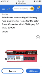
A 107 $ on a 2000W inverter; I'll think I would be suspesious if it will be any quality product, let alone a pure sin.

I'll try to get a pic of the inverter tommorow. And lookup the spec if I can find them.
 
Is that a pure sine wave inverter?
Yes it is. Thanks for the warning.
Uhm actually it is not... Probarbly why I got it for free. ?
On the other hand, I'm only going to run LED lights on it. So I'll just keep it for that.

To not keep opening new threads I'll just continue on this one. After all; it is still the same "trial and error project" ??

On the pic below you can see it clearly marked on the inverter. I'll guess my eye just caught "... sin wave... 1000W" and my brain didn't go any further. Well it can deliver plenty off power for the lights in my workshop so for now I just leave it like this.
But I'll keep an eye on it not to connect other stuff to it. Once I get the hang of the Solar-Virus I will get me more panels, decent batteries and then a proper inverter to power electronics for the house. I mean as stated; I'm still in the experimental phase and so far I've spend not more than just a few $ on connectors, the 50A security and the 150 fuse.
Will not use a 7 $ PWM on a 500 $ battery as also not a 100 $ alibaba inverter on 5000 $ of household appliances?
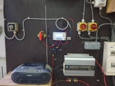

20220408_194030.jpg

So as follows;
1, The panel cable comes to the PWM through a main switch so I can shut it off.
2, From the PWM throught the 50A safety switch to the batteries,
3, From the batteries to the inverter via a 150A fuse. There was no 125A available at time of ordering, but I think it will be fine. (If not please comment)
4, From the PWM to a light switch that powers a 12V flood light.

---EDIT--- I have another battery switch. I like to put that between the battery and the inverter. Would I put the switch before or after the fuse?? THANKS ---EDIT---


I know a lot of people advise against using the power outlet on your SCC but 50 watts must be possible, not ? If it is really that bad why do they provide it in the first place? I like to use the programmable mode to have 1 or 2 hours of light outdoors in the winter. (please comment)

The 2 big square red switches are now powered of the grid. they switch the wall outlet on and off where the LED strings are on.
I will rewire them to the inverter as soon as I can find the parts needed for that. For now I'll be using a extension cord.


By the way I ordered a 125 A fuse from amazon that was so small I couldn't even get the cable connector for a 125A wire on that. See the difference in the picture with the second one. ( first one is on its way back to amazon)
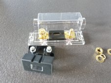
20220408_171742.jpg


Final question for today:

I have the following Amp/Volt meter LINK
It says 200 A but there is a 12AWG wire on this thing.
I like to connect it so I can monitor the inverter. I want to see how much amps it pulls as I have the lights on

But have no clue how to wire this thing. Please advise.
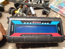
20220408_194322.jpg


Again thanks for the patience and the input. Will keep you updated on any progress.
 
Resistance loads are the only secure thing to do with modified sine imho
What do you mean by: Resistance loads ?? Is that what they explain in THIS article?

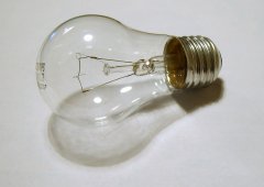
They write about "incandescent lights" --> that is a normal lightbulb.
lightbulb.jpg Okay still have those.

Then I will keep my LED string safe untill I get a proper pure sin wave inverter.
 
My question for today:

I have the following Amp/Volt meter LINK
It says 200 A but there is a 12AWG wire on this thing.
I like to connect it so I can monitor the inverter. I want to see how much amps it pulls as I have the lights on

But have no clue how to wire this thing. I cannot put it just before the inverter wich has 6AWG wire.
Please advise.

20220408_194322.jpg
 
Do you have the instructions for that? The devices I’ve seen for measuring current and voltage require a shunt. That would need to connect to a shunt and battery power I think. You’re on the right track. The best way to learn is to put something together and play with it. A dc amp clamp meter is really cool to play with when you’re learning about dc current flow.
 
Based on this image (from the link he gave), I think they meant for the current to pass through using the red and black wires.


"Courant: 0-200A, courant continu 50A. Tension: 0-60V. Résolution 0.01A. Le courant peut déterminer la capacité de la batterie, le courant continu peut déterminer le temps de décharge et le courant instantané maximum peut déterminer la structure interne de la batterie pour protéger le circuit."

I don't speak (or read) French, but 50A continuous 200A surge? I'll buy that.

"It says 200 A but there is a 12AWG wire on this thing."

Oh, is that 12 awg not 8 awg? In that case, 50A would be a bit much.
Yeah. It does seem that the red and black are line and load but 12awg is too small for 50, let alone a surge of 200. I saw the 3 pin connector in the photo and thought that might be for the shunt.
 
Could be shut, could be data port, could be power. Was there an instruction manual? I didn't know what to look for in French.

Is that really 12 awg? Did you check it with calibrated wire strippers or anything like that?
12 awg has ampacity 30A, and will certainly handle 100A peak no problem, probably much more. 100A and above is what causes magnetic fast-trip of a 20A breaker. 95A, and it takes a number of seconds for thermal trip.
If just a bit larger than 12 awg, like 1.3x the diameter, it could handle 60A no sweat (no sweat, but it would have 60 degree C rise in a cable).

Actually, 12 awg single wire in free air has ampacity 40A:


So wire it up to a battery and test it with a modest load.
I’m with you. It might work but I’d rather heat my toaster not my wires. :)
 
Sorry guys, yes bit funny right a link to the French version of amazon...:sleep:?

200Amp Volt meter kopie.jpg
200Amp Volt meter page 2.jpg

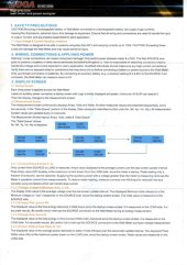
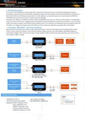
In the pictures the manual.

And yes really 12AWG, is printed very small, but with a photo and zoom I double checked.
Thats why I'm concerned about putting 200 Amp through this little thing.

It is to keep an eye on the 12V --> 220V inverter. Which with 1000W can go up to about a 100 Amps and that inverter has indeed 6 AWG connection wires.
 
Was there an instruction manual?
Yep, and in English. (See reply)

Is that really 12 awg? Did you check it with calibrated wire strippers or anything like that?
No sorry I did not.

Yes I know these tables. With a little common sense one should understand you cannot put 200 Amp on these little cables. But to double check, I looked it up.
That why I have put the question out.
According to the manual I should connect it between source and Load.
According to the table I should not use these little cables...
 
To not to keep opening new posts with newbie questions, a dug up my old topic again.

After running on all the cheap stuff for a while I want to take the next step. But while looking into some solar panels I came across this:
(It was all in french, just did a quick translation)
Informations techniques:
  • Power max: 150 W
  • Tension max: 18,11 V
  • Electric Curant max: 8,28 A
  • Open circuit Tension : 22,48 V
  • Short circuit (? ) Courant de court-circuit: 8,79 A
  • Dimensions: 1330x670x35 mm
  • >>>> Efficacité de panneau solaire: 18,9 % <<<<<
  • Tolérance de puissance: ±3 %
  • Diode de dérivation intégrée: 2
What does: Efficiancy of solar panel 18,9% mean??

Is that how efficiant it really is?? So 150W x 18,9% = 28,35 Watt ?? Well that is really bad isn't it??
I know it doesn't deliver the 150W but 28 ?

Please correct me when I'm wrong. :unsure:
 
Back
Top