diy solar

diy solar

Correct wiring…..?

DeanNelsonrn

New Member
Joined
Jan 20, 2021
Messages
42
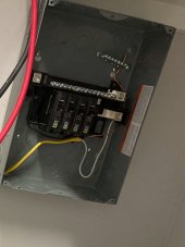
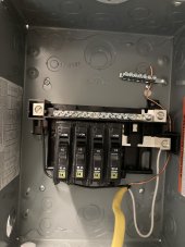
I KNOW …..I should have a Electrican look at this …..BUT…..where I live they are scheduled 4 months out and they don’t really “do” solar…..?.


Just wanted another set/sets of eyes on this…please and the wires wil be a lot cleaner.
.
 

Attachments

  • 8F4C2D6B-FB58-4066-8DAE-F48722D27EF8.jpeg
    8F4C2D6B-FB58-4066-8DAE-F48722D27EF8.jpeg
    199.5 KB · Views: 29
What are you trying to do?
What is that? 12ga feeder from inverter to a breaker panel I’m assuming?

What are you trying to do?
First up I can’t see the black well.
Second use longer unsheathed wire section and route it neatly and clearly- keep it in its own path with nice bends/routing so when 18 other conductors are present it ain’t a bird’s nest.
There should be no sheathed wires in a box

But I cannot tell what you’re attempting here, at least on my phone… it appears that you are attempting to supply a breaker panel? Or sub?
 
Is that the input power?
It looks like you might have the hot (black) and white (neutral) reversed. But can't really tell from the picture which is the common connector for the breakers. If you pop the breakers out, whichever terminal goes to the top bar of the breakers should be the black wire. The white should be on whichever one connects to that long bar above the breakers with all of the screws.
 
Last edited:
0F37244B-685C-4390-A4A4-8708259DA869.jpegMy apologies .. looked at my first question which gave no context!?!….

1. I want to wire my inverter into a 100 amp breaker box ( 4 120vac 60hz 15 amp circuits )
2. Are the the correctly wire connections..
 
where is your grounding?
is this a subpanel or completely isolated? (this will decide on how you do your ground bonding with neutral).
there should be a DC fuse in there somewhere if that is a DC input into the rich solar box (do you need a precharge resistor for the solar box?).
 
What’s the watts on the inverter?
Set that wire aside and use a longer piece so you can install stuff like nasa did it. It’s the same exact work, just some forethought on neatness and future ease is required.
But 12ga is a 20A wire and I don’t see where it has a main breaker? Main may not be required depending on inverter and I didn’t look it up to guess what it is.
 
where is your grounding?
is this a subpanel or completely isolated? (this will decide on how you do your ground bonding with neutral).
there should be a DC fuse in there somewhere if that is a DC input into the rich solar box (do you need a precharge resistor for the solar box?).
Completely isolated…..

And here is fuse
where is your grounding?
is this a subpanel or completely isolated? (this will decide on how you do your ground bonding with neutral).
there should be a DC fuse in there somewhere if that is a DC input into the rich solar box (do you need a precharge resistor for the solar box?).
 

Attachments

  • BF6F4619-08FF-4658-BB9B-FB1B43A53B79.jpeg
    BF6F4619-08FF-4658-BB9B-FB1B43A53B79.jpeg
    116.4 KB · Views: 19
  • 618D63BA-3A43-4430-93A8-1F809085BE4F.jpeg
    618D63BA-3A43-4430-93A8-1F809085BE4F.jpeg
    115.6 KB · Views: 19
That fuse on the solar cables to the charge controller? Or between batteries and inverter?
 
where is your grounding?
is this a subpanel or completely isolated? (this will decide on how you do your ground bonding with neutral).
there should be a DC fuse in there somewhere if that is a DC input into the rich solar box (do you need a precharge resistor for the solar box?).
That fuse on the solar cables to the charge controller? Or between batteries and inverter?
Between battery and inverter
 
Now that I can see better with that last picture, it still looks like you have neutral and hot reversed. The hot (black) should go to the inputs of the breakers. I can see the bar for the breakers inputs goes to that right connector that you have the white wire. Where you currently have the black wire, I can not tell if it is part of that neutral bar or not.
 
Now that I can see better with that last picture, it still looks like you have neutral and hot reversed. The hot (black) should go to the inputs of the breakers. I can see the bar for the breakers inputs goes to that right connector that you have the white wire. Where you currently have the black wire, I can not tell if it is part of that neutral bar or not.


Perfect ty
 
Now that I can see better with that last picture, it still looks like you have neutral and hot reversed. The hot (black) should go to the inputs of the breakers. I can see the bar for the breakers inputs goes to that right connector that you have the white wire. Where you currently have the black wire, I can not tell if it is part of that neutral bar or not.
 

Attachments

  • image.jpg
    image.jpg
    128 KB · Views: 10
Now that I can see better with that last picture, it still looks like you have neutral and hot reversed. The hot (black) should go to the inputs of the breakers. I can see the bar for the breakers inputs goes to that right connector that you have the white wire. Where you currently have the black wire, I can not tell if it is part of that neutral bar or not.
Like this sir?
 
Like this sir?

I still can not tell if that lug you have the white wire connected to is part of that neutral bar (to the right). It does not look like it. The larger lug on the right side is part of it.

Also that bare ground is too close to the hot terminal. If you must come in from the bottom, leave all of the insulation on and bring the cable up on the right above everything, and then loop back down toward the connection points.
 
I’ll move the negative wire thank you…

Here are pictures without breakers
 

Attachments

  • 7FA392C6-0B37-4E2E-A821-E24990A01783.jpeg
    7FA392C6-0B37-4E2E-A821-E24990A01783.jpeg
    154.9 KB · Views: 10
  • 18C91D8C-D581-4359-A61A-2D4C09B11306.jpeg
    18C91D8C-D581-4359-A61A-2D4C09B11306.jpeg
    115.6 KB · Views: 10
  • F0D2746E-F2C2-46ED-88D7-537A3D5BC12B.jpeg
    F0D2746E-F2C2-46ED-88D7-537A3D5BC12B.jpeg
    179.3 KB · Views: 10
  • 990D8A75-CE17-4916-8C0D-F61CD10DBB27.jpeg
    990D8A75-CE17-4916-8C0D-F61CD10DBB27.jpeg
    211 KB · Views: 9
@DeanNelsonrn is that a split phase panel?
Is it a plug on neutral panel?

I think we should do some continuity tests to see what you have before you energize anything.
 
@DeanNelsonrn is that a split phase panel?
Is it a plug on neutral panel?

I think we should do some continuity tests to see what you have before you energize anything.
Yes I will for sure test before ANY loads…. Here’s version 1.09876!
731FCB3F-34C1-45B7-9E26-7D57557CA52D.jpeg
 

Attachments

  • E5410BC4-932F-4AE5-B393-E0A1B02D7212.jpeg
    E5410BC4-932F-4AE5-B393-E0A1B02D7212.jpeg
    111.3 KB · Views: 6
Back
Top