diy solar

diy solar

Crimp Alone -vs- Crimp + Solder

Survival_Research

New Member
Joined
Nov 19, 2022
Messages
5
Hi, I know this issue has been covered many many times.
I would be interested in reading authoritative studies that recommend NOT performing both a high quality crimp plus high quality soldering for high amperage DC lugs.

Coming from a marine and aerospace environment I am very very familiar with the rationale why soldering is not recommended in those environments which have to do with vibrations weakening the strands over time at the point where the solder ends and the wire goes into the insulation. Generally the other rationale for not soldering refers to the problems with the high heat needed to solder 2/0 or 4/0 lugs creating issues with the insulation on the wire. And the already mentioned other issue being that it creates a brittle area at the end of the solder and the beginning on the wire that leaves the soldered area. Both issues can be addressed with a heavy duty heat shrink that extends a little further down the wire.

I am less convinced however of the reasons why in an application with high DC amperages and no vibration and possibly high humidity and or proximity to coastal (salt water humidity in the air) that a high quality crimp plus the addition of a high quality silver lead tin rosin solder would make for a connection that would be inferior to a crimped connection alone.

From an intuitive reasoning it would seem that whatever voids that would certainly exist between the circular conductors of each strand of wire in even the most highly compressed crimp would still contain some oxygen which, in high humidity environment, can oxidize the copper surfaces in that crimp or wick in moisture which open the possibilities for corrosion and further oxidization to take place over time.

It seems from an intuitive sense that to fill that space with a more cathodic (noble) metal (which is the function of the silver in the lead tin solder alloy - to increase its cathodic property) may address more potential issues that it would create. The reasoning would be that if those gaps were filled with metal it would create a connection with less resistance therefore would be less prone to failure and would also at the same time decrease the amount of oxygen which could enter those spaces between the round strands of the wire in that lug.

The difference may only be that the wire can withstand a few more amps and resist corrosion for a few more years but it seems that from an engineering and reliability standpoint that such increases in current capacity and decreases in possibilities of corrosion may offset concerns over vibration especially in a no vibration environment such as a home solar installation.

I am always looking for the optimal solution so I may be overlooking some issue with solder which would contraindicate its use so I am definitely seeking as much information as possible on this matter. But so far most of the reasons against its use fall under those that I have described above and would not apply in certain applications such as a home system.

I did wiring for Grumman Aerospace for many years and most connections were crimp only but I remain unconvinced that for a high amperage DC lug that a high quality crimp with the addition of a high quality soldering would be a bad idea.

From an intuitive standpoint it would seem that it would be preferable to perform both the crimp and the soldering.

I could be wrong - I am very interested in best practices so any information as to the science of why the dual "crimp + solder" method is less preferable to a crimp alone, would be fascinating and enlightening reading.

Thanks in advance for anyone who has these studies to share.
 
Last edited:
Back when I was an auto mechanic for many years, I always had the habit of soldiering heavy lugs after crimping them. But as you said, you do have to be careful about the vibration/movement aspect, because wires can fail near the end of the soldier joints, especially with smaller sized crimps.

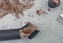
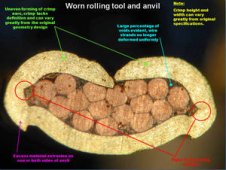
But after some years, I had learned that a properly crimped joint should fuse all the strands together (with no airspace between strands), and that there is really no benefit from soldering.

Refer to this video (at this point in the video), the guy demonstrates by cutting open various connectors at the crimp point where you can see that crimping should squeeze all the strands and fuse into a solid.


I don't soldier crimped wires together anymore. I will only soldier smaller wires together sometimes (if using twisting method and not using a crimp joint), and I don't soldier all the way to the ends on twisted connections. When I use that method (only on smaller wires), I join the wires end to end, with a long tight twist maybe up to an inch long, then I will only soldier the middle of the twisted section, so the ends on each side of the soldier are bare in the twisted area, then I use the heat shrink that has the hot glue in it to bond it all as a unit, well into the insulated section of the wire, to provide strain relief.

And don't ever put these joints in areas where the wire can have any movement.

That's just my methodology though, everyone has their own way I guess...
 
Last edited:
To add to this, when I crimp larger terminals like 1/0 on up, I just use a hammer crimper, but I do two hammer crimps side by side on the lug, to get more fusing area.

One other disadvantage I have seen to soldiering large connector lugs, is, if you're not careful, the user gets the wire too hot and sucks the soldier up into the cable, and it gets stiff, and can create a stress break point area up inside the wire. You have to keep the wire cool if one does try to soldier. But I never hassle with it anymore.

On smaller 'big' wires, like maybe 1 to 10 awg, I use a hydraulic crimper and it does great.
 
Last edited:
I can relate my personal experience, in a high amperage no vibration installation. One of my first electronic tech jobs, I was maintaining high powered Television transmitters. The transmitter had a total of ten 50A DC supplies. Very simple, just a transformer, large rectifier, and some filter capacitors. The rectifier and wires attached to it were a regular maintenance item. The wires would corrode/turn green and break at the crimp. When I first started, I noticed that they were crimped only, so when I serviced them, I did the crimp and solder thing. The crimp and solder job lasted about 6 months, and crimp alone lasted a couple years. By the time I "fixed" them all, I was fixing one twice a month. I went back to crimp only and that worked much better.

Now, most of the work I do is on boats, where soldering is forbidden because of vibration. But I don't think it is a good idea ever. Also noting that like Samsonite says, a proper crimp has no space for any solder. All you are doing is heating the copper, which will both weaken it and cause it to start oxidizing.
 
I solder (and crimp) my MC4 connectors for my PV array wiring - because they're hard to reach, out in weather/wind (could flex a bit) and I did so because I hope to never get arc faults or touch them again as they're difficult to reach :)

My 4/0 AWG battery cables or 2/0 inverter cables (e.g. welding wire stuff) I just crimp. Easy to check for heat (bad connections).

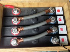
For some reason, I crimped and soldered the lugs on my DIY 18650 battery pack busbars (6awg bare twisted copper).
 
I can relate my personal experience, in a high amperage no vibration installation. One of my first electronic tech jobs, I was maintaining high powered Television transmitters. The transmitter had a total of ten 50A DC supplies. Very simple, just a transformer, large rectifier, and some filter capacitors. The rectifier and wires attached to it were a regular maintenance item. The wires would corrode/turn green and break at the crimp. When I first started, I noticed that they were crimped only, so when I serviced them, I did the crimp and solder thing. The crimp and solder job lasted about 6 months, and crimp alone lasted a couple years. By the time I "fixed" them all, I was fixing one twice a month. I went back to crimp only and that worked much better.

Now, most of the work I do is on boats, where soldering is forbidden because of vibration. But I don't think it is a good idea ever. Also noting that like Samsonite says, a proper crimp has no space for any solder. All you are doing is heating the copper, which will both weaken it and cause it to start oxidizing.
Interesting. Thank you for that info. With solder there is also the introduction of a dissimilar metal to the copper so I can see how that can be problematic as well. I wonder how tinning fits into the equation, theoretically the tinning of copper is itself the introduction of a dissimilar metal which theoretically is less desirable than having only one type of metal.
 
True swaging liquifies the soft copper and bonds nearly as a weld would - introducing tinning metal whose electropotential series react below Cu would be such small proportions any nodules would housekeep to keep the copper pristine - and/or heavy plated lugs on bare copper strands that do 'solder' the surface strands into the barrel metal when swaged are UCR in industry - and no, not talking about 'hamner crimp' but something that completes the swaging in 2 or 3 seconds...

Working on 750VDC subway cars and resistor load banks it was heavy plated lugs and a hydraulic crimper that wouldn't blink at 500 or 1000MCM cable, then the cables were exposed to all weather & some high-duty usage - once the surfaces oxidized it stopped there for years and years of service - didn't look pretty but kept running...

I ran across some ancient 2000v 3ph mining cable - 4 strands of ultra-flexible 4/0 in silicone sheathing under armored hard rubber & the conductor strands were lubricated & passivated with something that would not wash or burn off (yes the copper had been run hot for years and starting to crystallize & work harden) - I ended up using a 2% silver solder paste in non-corrosive flux applied before crimping, double crimped along the barrel and then hit it with a torch until visible paste soldered in at the barrel opening. Six years later zero change & running cool, always in an unconditioned room/vehicle...

They make a closed barrel lug series that have a pre-sized solder/flux pellet - clamp lug upright, toss in pellet and it turns the lug into a solder pot to push the conductor into and uniformly solder the lug - always wanted to try that, not sure if it'd be for maritime or skyscraper long runs etc. or what...

B559192B-0639-46A0-B3C3-481C79F532DC.jpeg
5F8F5450-EA23-4474-8CC8-E5CB0912BB26.jpeg
 
Interesting experiences. Mine was in a metal plating facility, a giant steaming pile of corrosive everything imaginable. A textbook hydraulic hex crimp on a big low volt power supply to say a steel cleaner tank (6 volt 400 amp) would be hot to the touch with crimp alone in 12 hours. I did with a salesman of the coolest crisper I’ve ever seen. He did the grounds, I did the positives on it. 4/0 copper lugs, He crimped, I used a hammer and cheap hammer punch and good solder. The next morning his connection was hot, mine was ice cold. This tank was on 24/7 with varying amp loads depending on how much was in it. Rarely maxed. In a week when he returned to sell me the crimper I said to touch both crimps, his was rainbow colored and he wouldn’t touch it and steaming, mine was ice cold And I put my hand on it. No sale.

My normal was a copper lug, smash it with a mini sledge to take up space in the lug and set the strands together, put it In the hammer punch die and smash it like I caught it sneaking in my daughters window late at night, solder with a map gas torch (just hot enough, careful not to overheat) and slide 4” piece of heat shrink with glue in it over the joint and wait for the glue to begin to ooze out.
I had near zero failures with this method in this environment. I understand why it’s not recommend in some situations, but In this one it was absolutely the best option. Nothing had vibrations or movement.
 
Yeah, just smash it with a sledge hammer. It's not REALLY a precision connection.
 

Attachments

  • X-ScanSoftware_ScreenShot5.jpeg
    X-ScanSoftware_ScreenShot5.jpeg
    206.5 KB · Views: 37
  • crimp-photos-worn-rolling-tool-and-anvil.jpg
    crimp-photos-worn-rolling-tool-and-anvil.jpg
    19.5 KB · Views: 38
I can relate my personal experience, in a high amperage no vibration installation. One of my first electronic tech jobs, I was maintaining high powered Television transmitters. The transmitter had a total of ten 50A DC supplies. Very simple, just a transformer, large rectifier, and some filter capacitors. The rectifier and wires attached to it were a regular maintenance item. The wires would corrode/turn green and break at the crimp. When I first started, I noticed that they were crimped only, so when I serviced them, I did the crimp and solder thing. The crimp and solder job lasted about 6 months, and crimp alone lasted a couple years. By the time I "fixed" them all, I was fixing one twice a month. I went back to crimp only and that worked much better.

Now, most of the work I do is on boats, where soldering is forbidden because of vibration. But I don't think it is a good idea ever. Also noting that like Samsonite says, a proper crimp has no space for any solder. All you are doing is heating the copper, which will both weaken it and cause it to start oxidizing.

Did you clean the flux/rosin off after soldering?

Leaving Flux on there causes verdigris rather quickly.
 
A PROPER crimp is also called a cold weld.
As in airtight connection. If it's airtight, how you gonna solder it?

There is no such thing as a cold weld unless you're referencing a spot weld in which case those are called welds because of the short length of time and small area that heat is applied and the fact that no filler metal needs to be heated.
 
Crimped and soldered is best but such discussions inevitably lead to a Montague and Capulet situation.

Don't crimp unless you have a nice crimper and know the proper amount to crimp each connection.

Don't ignore other aspects of the connection such as complete insertion of the strands,

Quality of the terminal i.e. make sure they are of hefty gauge..I also prefer tinned

And make sure the hole for the hold-down bolt/stud matches the size of the fastener. Too big a hole is no Bueno.

Also deliberately oversize your cables so you're not running right on the edge. This leaves a bit of room for error.

Make sure your terminals have good quality bolts nuts and lock washers.

Somebody else mentioned the tug test. Yes, do this. This will verify that you adequate crimps and that your terminals are not made of weak metal or that you overcrimped and thinned out the metal and made it weak.
 
This is what I am DISagreeing to. If the crimp is properly done, there are NO voids that solder will flow into. Unless you just want to smear solder on the outside of the connection

explosion welding I believe can Create a good weld, I don’t have one. I tested the best (and silly expensive) crimped side by side with a low tech method, and it failed. there may be no air initially in the contact area, but they are not one metal, just a close fit. Heating and cooling through use creates expansions and contfaction, which then invites air and moisture. This leads to corrosion, slowly at first, and then faster as the joint degrades and corrosion Makes the resistance more and heat cycles worse.

If the crimp is perfect, solder would seal the outer lug area and prevent ingress. If there is micro spaces it creates a truer bond which not only Makes better contact with less heat, but keeps out air and moisture. ever go back and tighten copper lugs on breakers or large screw terminals? They are loose after a month of use and need resnugged. I use to work marine (small non commercial) and half my day was fixing wiring that became sporadic, inoperable, or just caught fire. Factory crimps, screw terminals, switch internals,,, trailers were usually 2 a day because the lights quit. I would replace them, solder, heat shrink, use compounds of anti oxidizing and such and then problems stopped and I only got to do routine maintenance and repairs.

Perhaps someone has a perfect crimp machine they can lend out that does perfect no solder crimps that never oxidise , maybe NASA has one, who knows, that under destructive testing on a scanning electron microscope shows a perfect joint and under 20 year accelerated testing never fails…
but for the average person with an average budget wanting a solid problem free connection, thats what I did.i recently had to do some work on a job I did 12 years ago (off grid lead acid battery bank) and while I had some terminal to lug corrosion the wires all were fine and didnt get a tiny bit warm under full load.

right now, under thermal scanning the only heat I have in my system is the perko A B switch, shunts, and panel wire connectors. I’m at a year and a half, in a challenging (but not salt) environment. I’ll let know how my expirament went at 5, 10, and 15 years if you like.
 
Last edited:
This might be a silly point on my part but we solder plumbing because the pipes cannot be crimped because they will leak.

OEM automobile manufacturers have crimped only cable connections but the terminals are very heavy gauge metal and are tinned. Older oem connections cast the lead terminal around the copper wire.
 
OEM automobile manufacturers have crimped only cable connections but the terminals are very heavy gauge metal and are tinned.
I also thought this for years, but after had open dozens of EV batteries, I can confirm than some Ford and GM cable connections are crimp and solder ?
 
Back
Top