diy solar

diy solar

Crimp Quality…?

I’ve never had problems as long as I use quality lugs (Ancor or Selterm) the right wire size, die and a good looking crimp. A good looking hex crimp has sharp corners with little to no extrusion or flash where the gap of the die is. The hex can be slightly flattened. You can use one of those cheap yellow hydraulic crimpers but be warned that most of the dies will need the gap cut down to reach the above criteria. Take your time milling or grinding the halves down because the “put it back on tool” sucks lol.
Take a measurement under load, at say 80 amps at 54 volts ( 2/0) take a reading across the lugs. I like the Kiaweets HD208D clamp meter, it can read .0001 Volt (Four places). Also very helpful for readings between the lug and terminal.(hint for low profile boss/terminals, use a metal shim with Kapton tape on one side to probe under the lug). What your looking for is the “ringer” out of the norm so you can build an acceptable standard. Internal resistance meters can say a lot, but the last word is a load test looking for too much voltage where it shouldn’t be.
 
  • Like
Reactions: JRH
Seems like you're putting way too much thought into this than necessary.
If you've got a good hydraulic crimper and have cut a few crimps apart and your technique is good, I wouldn't worry further.
Hook it all up and stress test the system to the max amps it will transfer and even higher if you can simulate fault conditions. Check all connections during testing, ideally with a thermal camera if you can.
Pass the stress test then no need to worry further.
For example I just finished crimping a series of 35mm2 connections for a camping battery. Stress tested the system to 200amps continuous for about 10mins to assess for warm connections. No issues, so put system into service. Done.
It sorta what I was Gona do as it’s seems its about all you can do..
I was just wondering if there were more exacting test one could do. It appears there may be but they are beyond the scope of what I need.. just trying to not assume on a topic I am not familiar with…
if you have never done it ,ya can’t know, but I’m seeing a common consensus on what to do… stressing it is what’s a coming and we will see how it handles it..
i will be fine..
thanks for your words…

Jim.
 
Last edited:
I’ve never had problems as long as I use quality lugs (Ancor or Selterm) the right wire size, die and a good looking crimp. A good looking hex crimp has sharp corners with little to no extrusion or flash where the gap of the die is. The hex can be slightly flattened. You can use one of those cheap yellow hydraulic crimpers but be warned that most of the dies will need the gap cut down to reach the above criteria. Take your time milling or grinding the halves down because the “put it back on tool” sucks lol.
Take a measurement under load, at say 80 amps at 54 volts take a reading across the lugs. I like the Kiaweets HD208D clamp meter, it can read .0001 Volt (Four places). Also very helpful for readings between the lug and terminal.(hint for low profile boss/terminals, use a metal shim with Kapton tape on one side to probe under the lug). What your looking for is the “ringer” out of the norm so you can build an acceptable standard. Internal resistance meters can say a lot, but the last word is a load test looking for too much voltage where it shouldn’t be.
I agree, all top tier products , lot of practice crimps cut in half , learning which way works best… then look for the standouts thst don’t look right from the norm… deal with them when you find em..
that's how they dealt with me in school .. I stood out.. so they dealt with me….ouch….
thank you.. wise words.
 
Micro-ohmmeter or thermal camera are your best options. It is interesting with the thermal camera on a fully loaded conductor-- you can see the individual crimps' effeciveness.
 
  • Like
Reactions: JRH
Micro-ohmmeter or thermal camera are your best options. It is interesting with the thermal camera on a fully loaded conductor-- you can see the individual crimps' effeciveness.
Trust me I know about the thermal stuff .. I used to have a great thermal image scope on a m14 .. it showed all I would like to see plus around the house stuff and heat leaks and many other things leaks and stuff. Plus it showed people at 500 yards.. ,but they are 3000 bucks and I sold it ..Three years ago.
bummer.
I will just have to get by with the red dot heat sensor ,a volt meter and the hand touch technique ..

thank you , Jim.
 
Until I did my PV/LiFePO4 install I had never crimped anything larger than about 12 gauge. Now I feel comfortable doing just about any gauge. I used lugs and cable from TEMCo Industrial and they all fit together quite well. The hydraulic crimper also came from TEMCo Industrial. I think the tool made allowances for the inexperienced installer.

The basic test of a crimp is, can you pull off the lug. None of mine wiggled one bit. I pulled like my life depended upon it.

I did the stress test on the system by charging my EV from the RV. No hotspots other than the heat generated by the inverter.

The crosswise measurement of the lug is interesting. I've never heard of that one. If you find out more, please share.

Cutting the lug apart and finding it to be OK is great for THAT lug. I've read that cutting the lug (with a saw blade) just smears/melts the copper wire and can make a marginal crimp look good. But it sure would point out a bad crimp when the lug goes flying off as it comes into contact with the circular blade.
I agree with what your saying… I have seen much of this myself in the last few days of crimping all day…
I have tested and cut open about 20 that I have both bought and made myself.. you can definitely learn a lot from looking at what works great and what doesn’t . Both due to technique and different crimpers. The one constant here is the lugs are all Selterm…. There are probably better ones and I know there are worse ones ,but thst is what I have for lugs.
Not having crimped a lot of wires in my life as I bought them premade for large sound systems or my sailboats battery bank, I bought 5 different lug crimpers last month to test them out and see which worked better …most of what’s on Amazon we all have seen.
None seem to do all gauges as good as the do a few gauges .. each seem to have their own wire size they like… some don’t like 8 gauge and some don’t like 1/0 or 4/0 …sorta like certain ammo and different guns don’t like each other…

the crimpers ran from 35 to 150 bucks each…price does not seem to make one better than the next in all things Thus far… To much to say here but my favorite is not the most expensive so far… I will probably end up with two types ..one for big wire and one for smaller ( 8-6-4 ga)

it is very interesting to test different techniques and crimpers to see what results in a good crimp and what looks awful after you cut them..…soon you see a pattern In your combination of stuff .

I am now seeing how you can sorta judge them from the process of doing it over and over …the feel of the crimp , the appearance and how things fit…at least that what I see at this point.…and I cut mine in half with a fine tooth blade at a very slow speed .. you can easlily see the insides and results . It’s clear as a bell when ya did right or did wrong .

I am finding out ,this is not an inexpensive ,quick or easy hobby to do well. “Well“ being the operative word.

J.
 
the crimpers ran from 35 to 150 bucks each…price does not seem to make one better than the next in all things Thus far… To much to say here but my favorite is not the most expensive so far… I will probably end up with two types ..one for big wire and one for smaller ( 8-6-4 ga)

I didn't buy crimpers to experiment with but it did seem like I took a chance with a couple of them due to lack of knowledge.

TEMCo Hydraulic crimper TH0005 (6 AWG to 600 MCM) - This is the big dog. Zero problems. Well worth the money. This has been superseded by the TH006.

Ferrules Direct FD2806HX Round Ferrule Crimping Tool (28 AWG - 6 AWG) - This is like the Ferrari of ferrule crimpers, and it cost like it too. After I bought it but before I used it I was kicking myself for buying such an expensive tool. But the round crimps it produces are perfect. I didn't think I needed round ferrule crimps but it turns out that I've had terminals that a round crimp just works better in.

Pro'sKit 300-144 Lunar Crimper, Wire Ferrules (10-6 AWG) - This produces square ferrule crimps. I used this for 10 AWG PV and 6 AWG welding wire going into breakers and my Victron solar charge controllers. Various dies fit in this ratcheting crimper.

All my insulated ferrules came from Ferrules Direct as kits. Good quality stuff!

Lunar Series Die Set for MC4 Solar Panel Contacts (14/12/10 AWG) - This die fit my existing ratcheting crimper (see above). It produces very good MC4 connections. Any issues are with the inexperienced operator. Crimping MC4 connectors requires some thinking. You have to match up the right female/male copper terminals with the right male/female plastic connector. I wasted a couple of the terminals before I got it right.
Thanks for the tips… I did simalar things when buying crimp tools.. getting good ferrules is not an easy task .. and getting good ferrules crimps for large ferrules can be a rather daunting adventure financially..

I don’t profess to know all the answer to most of these topics , I not even sure of some of the questions to ask on certain things… but I keep plodding forward with different levels of progress, and I will get there at some point. I have always been a project guy and working with my hands on things…..
but I will probably have a lot of extra gear and parts laying around here I didn’t need… HELLO EBAY, I’m back …

I will look up your products , but I’m pretty much done with buying lug and ferrule crimpers…I will say ,it’s been fun trying to understand this stuff…it’s a new area .. it’s the future…

thanks for your input… and your past help…
JIM.
 
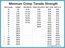
Pull/tensile strenght test is widely used to judge the crimp quality.
bigger sizes get bit impractical or you need to get bit creative to make suitable load.

with quality lugs I’d aim for MIL-xx specification, 875lbs for 4/0 cable
1661451826283.jpeg
 
When pull testing your crimps with really high force is there any concern about breaking some of the strands in the cable? Would it be considered destructive testing like cutting them open, or is it ok to use a cable that you dangled 400lbs from?

Going to be doing some large crimps soon and would like to test them but it worries me about breaking some of the strands and lowering it's current carrying ability.

Now I need to decide between hex and indent crimpers.
I’d consider it destructive test if taken to MIL-spec level: load can be quite torture on the terminals and they tend mangle and deform even if they would stay in one piece.

I’d use it as a check to verify your cable lug/crimptool/cable combination on a short piece of test cable. Tho you can do some sort of ”sanity check” with lower force for all of your crimps if you want.
 
I didn't even think of how messed up the lug itself would probably get good point. Maybe sacrifice a few and test until failure would be a good idea and then just a light tug for all the real cables as you suggest

It's good to know I'm not the only one who is obsessing over crimps.
 
Pull/tensile strenght test is widely used to judge the crimp quality.
bigger sizes get bit impractical or you need to get bit creative to make suitable load.

with quality lugs I’d aim for MIL-xx specification, 875lbs for 4/0 cable
I wonder if those apply for fine-strand wire. With 535MCM DLO cable I know that you couldn't trust the full stranding to carry load under tension in a compression lug.
 
Does anyone know or is there a way to test the quality of your crimp…?
i have about 70 to do this week for the wiring up my system, 4 ga to 4/0.
im using good quality everything , have practiced it a lot and have cut about 20 of the practice lugs in half to check the cold weld status .. I am trying to do it as good as possible ,but after you do them ,how do you really know, ( unless it’s an obvious screw up) ..I do a pull test , they look fine, but how do you know.?

is there a way to use a multi meter to evaluate resistance ( ( OHMS) before and after of the wire and lugs and whatever difference may exist before joining and after joining…

or is that even a meaningful test…

so much could show up as so many things with just one bad crimp being the culprit…

this ain’t cool…
there has to be a way to know more than just hoping it’s a good crimp..
But maybe I’m wrong…
thx ….Jim
don't buy the hydraulic crimper from Hyclat for 4/0 lugs...the number size 70 doesn't crimp tight enough. wire comes right out. don't sell size 65 or 60.
 
don't buy the hydraulic crimper from Hyclat for 4/0 lugs...the number size 70 doesn't crimp tight enough. wire comes right out. don't sell size 65 or 60.
Haa.. thanks… I’m all done a while back… crimping seems to be a bit of a mystic art sometimes… I bought like 5 of them and experimented and just used the one that worked the best … all is done and works fine … system runs great..but it still is a sorta spooky science…
 
don't buy the hydraulic crimper from Hyclat for 4/0 lugs...the number size 70 doesn't crimp tight enough. wire comes right out.
Yikes! I remember seeing a chart somewhere that showed a 'pull strength test' for various size of crimped lugs and for 4/0 i believe it should be able to withstand 800lbs of force before pulling apart!
 
Does anyone know or is there a way to test the quality of your crimp…?
i have about 70 to do this week for the wiring up my system, 4 ga to 4/0.
im using good quality everything , have practiced it a lot and have cut about 20 of the practice lugs in half to check the cold weld status .. I am trying to do it as good as possible ,but after you do them ,how do you really know, ( unless it’s an obvious screw up) ..I do a pull test , they look fine, but how do you know.?

is there a way to use a multi meter to evaluate resistance ( ( OHMS) before and after of the wire and lugs and whatever difference may exist before joining and after joining…

or is that even a meaningful test…

so much could show up as so many things with just one bad crimp being the culprit…

this ain’t cool…
there has to be a way to know more than just hoping it’s a good crimp..
But maybe I’m wrong…
thx ….Jim

I watched experts solve this issue 30 odd years ago... That 'Sloution' was at least 100 years old 30 years ago.

Build the joint, tension test the joint by pulling on it, then connect the joint, electrically load the joint and look for resistance expressed in heat.

Static electrical resistance testing (ohm meter on disconnected wire) ONLY detects conductor resistance per foot, and resistance of terminal ends.

You simply CAN NOT test the load carrying capabilities without a load test. It's that simple, and it's also the reason load testers exist.

Load that '200 Amp Capable' conductor at 200 Amps and you will get your answer rather quickly, if it DOESN'T heat up, it's carrying the load.

If it DOES heat up, you have issues somewhere because heat means FAILURE AT CAPACITY.

From the first DC grid systems (Edison) all heavy connections have been SILVER SOLDERED AFTER MECHANICAL CRIMP.

These generators are still in service today. See the NYC subway systems and other systems.

AC generators that have been in serves thst long also (Westinghouse-Tesla) do exactly the same thing. Mechanically clamp the conductors, silver solder the connections.

Fact. Silver conducts electrical current better, less resistance than copper. Copper is more common so cheaper.
This means copper is a compromise. Adding silver at critical connections LOWERS RESITANCE, PROMOTES ELECTRICAL CONDUCTION.

Fact. Silver Solder, and silver bearing electrical solder ONLY FILL AIR GAPS AFTER MECHANICAL CONNECTION.

Fact. Air gaps ARE NOT ELECTRICALLY CONDUCTIVE. Soldering with silver, high or low temp, turns gaps into conduction.

Fact. Silver solder (high or low temp) protects much more reactive copper from corrosion, impeded conduction.

Real Silver Solder takes temperatures the normal DIY type can't produce, it takes an oxygen fed torch or electro-magnetic induction heating to temperatures high enough for silver to flow.

Silver content, called silver content BEARING solder IS readily/commonly available and does lower temperature joints the same way. This is your soldering iron/jet torch lighter heat range.

Mechanical connection, THEN silver solder electrical connection, then environmental seal the connection, like glue lined heat shrink...

So, someone is going to spout the "Aircraft/Vibration No Solder" argument...

Application. Application. Application.

Exactly how hard do your solar panels get beaten? Did you mount them on a rock crusher so they see serious high cycle vibration? Do your batteries sit on top of a piston type earth packer? Does your battery do life support for 300+ people?

Comercial aircraft wiring is replaced on schedule, hours on the airframe. Are your battery cables replaced on hours of use or age schedule? Application!

The high amp, AC and DC generators see continuous use, in a vibration environment, for over 100 years.
The application is proven, the connection has been figured out, for over 100 years.
 
Last edited:
Back
Top