bestconcreteblock
New Member
- Joined
- Dec 5, 2022
- Messages
- 48
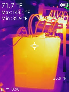
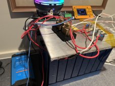
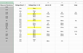
Just finished this crude test(see .pdf) for this Frey 36130190-60PF 60Ah Cell. These are power cells with 3C continuous discharge.
Looking at the data sheet discharge curve(also attached), I expected the terminal voltage to hold above 3.0V for more than half the test. That was not the case. Cell must have a little bit higher internal resistance than advertised. These were purchased directly from Frey via alibaba.
These cells have delivered around 62 Ah consistently with a 1/3C discharge rate.
Any thoughts?