diy solar

diy solar

Crude at this point, but my design needs scrutiny please

Stepandwolf

Solar Enthusiast
Joined
Nov 14, 2020
Messages
668
Saw the great help others got here, let me show you my diagram as it is now. I suspect there will be comments on fuses and gauges, and every thing else too :)

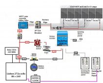
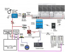
trailer solar wiring diagram_c.jpg


As of now, the panels are a bit uncertain as what I wanted wasn't available and then became available. In another topic, I will ask for help with panel configuration, but for sake of the current design, it is six 100w panels wired 3s2p. The specs for the panels are "max 600vdc, open ckt 21.6V, optimum 5.56A Short-Circuit 6.5A, series fuse rating 15A". I hope that gibberish means something to someone :).

My diagram shows an 8ga wire from the DC>DC as it is rated at 40A, however the wires in and out of the converter are 12 GA. Don't know if that means I can safely use 12ga wires or connect 8ga to their 12ga?

Any help will be appreciated.
 
We'll need a bit more information, take a look at this post/thread to get an idea of what: https://diysolarforum.com/threads/please-check-my-design.25650/post-302597, for example, the gauge cannot be verified without knowing wire type.

In 3s2p that's roughly 22x3=66V and 2x6.5=13 amps. Check the manual for the Victron, the proper gauge/wire-type depends on how long the surge rating can be sustained. Gauge for dc distribution depends on the watts the distribution supplies.

See What wire gauge should I use? (video). The video is really really good, I definitely recommend it.
 
Last edited:
I actually used that posting as the basis for mine. Thought in his case there was only one mention of wire type.

WNI 2/0 Gauge 5 Feet Black 5 Feet Red 2/0 AWG Ultra Flexible Welding Battery Copper Cable Wire

WNI 6 Gauge 5 Feet Black 5 Feet Red 6 AWG Ultra Flexible Welding Battery Copper Cable Wire

Those were both from Windynation and I have already bought.

I didn't buy the charge controller yet as I am trying to determine if I can run 6 panels or more. Seems the 100/30 Victron is adequate for six panels. The 10ga from the roof to the battery area was installed by the factory. I didn't check the actual wire spec, only looked at the ga. It is actually 10ga from the roof to a cabinet, then 8ga the rest of the way to the battery compartment.

I haven't bought the 8ga for the 110v as I don't know the best way to run it which would determine what I get. I don't even know if 8ga for 30a is overkill or not? I was looking at tri-wire and power wire. I will be running under the TT from the battery compartment to the TT's power control center. Debating running exterior rated Romex type cable, triwire in conduit, or two pieces of portable power cord (SOOW). Have to get the shore power from the power center to the inverter and then back again.

Sorry for the convoluted answer, but think I covered all your questions. I have spent an unbelievable number of hours viewing videos and reading blogs...thanks!
 
Recommend you put your fuse and then switch prior to the SCC input. As it is now, the Fuse could blow and you trip the switch, but the battery is still bein charged.

Looks like you have 24 volts with 2/0 wire going into the DC to DC converter, but then you have 8 gauge coming out. Not sure that is correct. Usually the thicker wire is on the lower voltage side.

Have you considered using an additional DC fuse box for 24 volt items? I added one for things like quick charge devices and 24 VDC lights. That also lets me wire in a 24 volt compressor fridge if I go that route.

For main battery power, I think you'll be OK with 2/0. For my 24 volt upgrade also with a 3000 watt inverter, I am putting in 4/0.

The ground out of the charge controller makes it look like you are doing a frame ground, but I'm sure you are not.

If you have Victron Smart products, the blue tooth dongle is unnecessary to interface with your blue tooth devices. If this is not the intent of the dongle, what is?

I also recommend doing a check with a voltage loss calculator for the panels you choose. I believe the intent of pre-installed 10 gauge wire is to run no more than 300 watts or a little more of panels. For my fifth wheel, I could not combine on the roof with 600 watts of panels and still use 10 gauge without a bit of possible loss. I ended up going with 3S2P with 100 watt panels and doing both runs of 10 gauge through the roof and then through the floor and combining in the Battery bay.

What is the device between the SCC and the battery prior to the wires splitting?

I like the idea of a breaker prior to the SCC. Although not required, its nice to have something to shut the panels off when storing it or doing maintenance. What type of breaker? I like the midnite solar DC breaker/
Frankly, there are two "remnants" in the drawing from where I copied it from. The bluetooth dongle was in the other person's picture. So was the ground you see. I know I should have a chassis ground somewhere, probably on the negative lug. I don't have that dongle, but I was sold the Bluetooth adapter for the inverter. The sales guy said I needed it?

>Recommend you put your fuse and then switch prior to the SCC input. As it is now, the Fuse could blow and you trip the switch, but the battery is still bein charged.

Not sure if I follow you there. Between the panels and the SCC is a breaker which I am using more as a disconnect. Are you saying power will go past the breaker to the battery?

I have no 24V items other than the converter. Sorry for my poor drawing. I am not showing a gauge going to the converter, only the 8ga going from the converter to the fuse panel. Where it says 2/0, that is the horizontal line, i.e. the wire from the BMS to the inverter.

re: 4/0 vs. 2/0. It is my understanding the max draw from the inverter is in the 150-175a range, well under 2/0. It isn't labeled on the diagram, but the wires on the BMS from the factory are 2ga.

Thanks for the advice on the panel wiring. I was hoping to use the factory solar wire to avoid a new hole in the roof. I guess considering putting in a bunch of bolts for the panels, put in a new hole for a gland might make sense. It also sounds like I can't put additional panels together, so I might end up with a set of 4 panels separate than the 6 panels.

Thanks so much for all the tips and advice. I will clean up my diagram to hopefully make it less confusing.
 
With a 30 amp supply should already have a breaker so that 30 amp breaker at the power inlet seems redundant. Also the Multiplus can be set to restrict power to 30 amps so double redundant. Then the existing breaker panel probably has a 30 amp main breaker to boot. #10 wire is perfectly fine and ordinary for the 30 amp incoming power.

Is that a 300 amp Class-T fuse? I would tighten that way up. That thing will pass 500 amps for a full minute before it opens. The BMS will cut off first every time. I would remove the fuse or a cable to cut power to the inverter instead of having the switch in the inverter 24v feed. Might seem handy at first but you could go years without using the switch and it adds a couple more connections etc to have issues or just provide a sliver more resistance.

Just some random thoughts, nothing dangerous either way.
Since I am dealing with some of the TT factory wiring, I am pretty sure they have a breaker on the 110V side. I wasn't intending to add a 110V shore power breaker, I am just assuming the TT was already protected by one that I would just use as is. Perhaps for purposes of the drawing, it isn't shown where it is.

The 300a fuse is an ANL. I don't know Windynation/Prowse suggested option.

Appreciate every comment as I am here to learn and get it right.
 
I would think a 250 ANL would be fine considering the 250 BMS. Max draw at 150-175 +20% = 210 amps.
In response to your comment, and an earlier one and cable size for the inverter, I happened to have the manual here for the 3000va/24/70 model.

Recommended battery capacity 200-700a
Recommended DC fuse 300A
Recommended cross section 50mm for up to 6m cable length.

So in answer to chrisski, 2/0 should be fine considering they are suggesting 1 ga.

I appreciate your suggestion on the amperage and I understand your calculation, but Victron specified 300a.
 
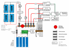
OK, I have cleaned up and added your suggestions. Here is a new version of the diagram. Wasn't sure about what to put between the SCC and the bus? I should also mention that the factory BMS cables are 2 ga which is not shown.

trailer solar wiring diagram_d.jpg
 
Last edited:
I don't have that dongle, but I was sold the Bluetooth adapter for the inverter.
THat may be true. I do not have the Victron Inverter, just three SCCs and the Battery Monitor. I think your sales guy may be correct.
Not sure if I follow you there. Between the panels and the SCC is a breaker which I am using more as a disconnect.
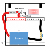
This is how I have my fuse and battery set up. This is still the 12 volt system I have now, not the 24 volt system I'll have done in a couple of months.

First thing off the battery is the fuse. Next thing is the Master on off switch. That way with the fuse, if something shorts to ground somewhere down the line the whole system is dead. Where you have it, the SCC is before the fuse and off switch. The good thing about the off switch where I have it, when shut off, no power goes into or out the battery. In your diagram the SCC is still charging the battery. If I'm working on the batteries, I want no power going to it.
1626661313866.png
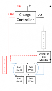
On those other 7 terminals on the bus bar, I hook my charge controller:
1626661431458.png
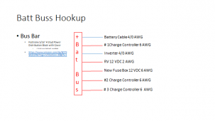
This is how I have the 7 posts of the busbar wired with the one spare not shown:
1626661495353.png
THe new fuse box labeled 12 volts, I only hooked dual voltage12 volt and 24 volt items. That way, when I turn on 24 volts, they still work. The empty post on this bus bar will have a 24 volt to 12 volt converter hooked up that will still run my RV's 12 volt items like lights and leveling jacks.

I also have an ANL fuse now, but will upgrade that to a Class T. The ANL fuse may be fine with a lead acid battery bank, but a class T fuse is rated for a lithium. ANL fuse could blow, but there's enough amperage on the battery the current could arc across the gap.

I'm also not sure a 32 amp breaker is easy to find.
 
THat may be true. I do not have the Victron Inverter, just three SCCs and the Battery Monitor. I think your sales guy may be correct.

This is how I have my fuse and battery set up. This is still the 12 volt system I have now, not the 24 volt system I'll have done in a couple of months.

First thing off the battery is the fuse. Next thing is the Master on off switch. That way with the fuse, if something shorts to ground somewhere down the line the whole system is dead. Where you have it, the SCC is before the fuse and off switch. The good thing about the off switch where I have it, when shut off, no power goes into or out the battery. In your diagram the SCC is still charging the battery. If I'm working on the batteries, I want no power going to it.
View attachment 56843
On those other 7 terminals on the bus bar, I hook my charge controller:
View attachment 56844
This is how I have the 7 posts of the busbar wired with the one spare not shown:
View attachment 56845
THe new fuse box labeled 12 volts, I only hooked dual voltage12 volt and 24 volt items. That way, when I turn on 24 volts, they still work. The empty post on this bus bar will have a 24 volt to 12 volt converter hooked up that will still run my RV's 12 volt items like lights and leveling jacks.

I also have an ANL fuse now, but will upgrade that to a Class T. The ANL fuse may be fine with a lead acid battery bank, but a class T fuse is rated for a lithium. ANL fuse could blow, but there's enough amperage on the battery the current could arc across the gap.

I'm also not sure a 32 amp breaker is easy to find.
I took my design from bits and pieces from various other designs because each design was a different configuration. The one design I really liked and was done very professionally shows the SCC and bats on the same side of the master switch.

8fu93ep5a1p61.png

I probably wrongly assume that anyone who can make a pretty drawing probably also has some configuration knowledge, but that isn't necessarily true. His design, like mine, has the breaker before the SCC, and a breaker AND fuse before the bus. I am still debating what if anything is needed between the SCC and the bus as some designs have nothing there and this guy goes the other way with fuse and breaker protection.

Thanks Chris
 
Just keep the different ideas in mind.

I spent a lot of time planning placement before my parts showed up. I did pricise dimension drawings on the computer and even did cardboard cutouts, and still when I put the components in, it changed a little. Part of this for me was even though I had very flexible welding wire, I still did not have as much room to work with on the larger wire as I expected. I just could not bend this thick wire as sharp as I thought.

I guess there could be reasons he would set it up that way. One is if this system were stored a long time, the master off switch would seriously cut down on the parasitic draw And let his batteries be charged by the panels.

Also with his system, lithium batteries are real hungry and can make an alternator work so hard it would heat up and burn up. THere’s supposed to be something like a DC to DC converter between to limit the amount of amperage.

One other thing on hid drawing, I’d size the fuse up to at least one size above 150 amps. When I run my microwave at 12 volts on my 2000 watt inverter, I see 155 amps at the battery which will exceed the class T fuse size in his drawing. When I look on the class T fuse chart on Blue Sea, a fuse blowinng could take sever minutes if its just barely over the amperage. It’s OK to size the fuses above the amps you safely expect to see.
 
I wasn't providing his diagram for anything other than to show the SCC and bats on the same side of the switch. That was the second suggestion regarding the class T fuse, but I don't think I have one. I think the ANL fuse in my diagram has different blow stats? The 300 ANL fuse was from both Will and some other design.
 
Just keep the different ideas in mind.

I spent a lot of time planning placement before my parts showed up. I did pricise dimension drawings on the computer and even did cardboard cutouts, and still when I put the components in, it changed a little. Part of this for me was even though I had very flexible welding wire, I still did not have as much room to work with on the larger wire as I expected. I just could not bend this thick wire as sharp as I thought.

I guess there could be reasons he would set it up that way. One is if this system were stored a long time, the master off switch would seriously cut down on the parasitic draw And let his batteries be charged by the panels.

Also with his system, lithium batteries are real hungry and can make an alternator work so hard it would heat up and burn up. THere’s supposed to be something like a DC to DC converter between to limit the amount of amperage.

One other thing on hid drawing, I’d size the fuse up to at least one size above 150 amps. When I run my microwave at 12 volts on my 2000 watt inverter, I see 155 amps at the battery which will exceed the class T fuse size in his drawing. When I look on the class T fuse chart on Blue Sea, a fuse blowinng could take sever minutes if its just barely over the amperage. It’s OK to size the fuses above the amps you safely expect to see.
I hadn't looked at the alternator on his design. You are right, he should not have the alt directly wired to his bus. He needs a product like the Orion that controls or more properly, limits the alternator charge. His design would allow the alternator to overcharge the batteries or put too big of a draw on the alternator. In my case, due to the 24V battery, an alternator charger would have to be stepped up to the 24v bat.
 
Just a few thoughts on this diagram:
  • Did you confirm the panel amperage with the temperature correction factor (example calculations)?
  • You have 6 AWG off the SCC, it'll work, but over specced for 13 amps.
  • A 3kW inverter at 24V can continuously pull 125 amps. The 2/0 wire is good, but check the 300 amp fuse (the fuse/breaker shouldn't be higher than the wire, it's meant to protect the wires). I'd check the inverter manual, they can pull more current for surges, but usually the time period is so short the spec should just be a little more. The multiplus is a quality unit, so it might have more oomph.
  • Be sure the battery switch is rated for the voltage/amperage and tested by a lab like UL/ETL, you really want that to work if needed.
  • 3000 watts at 240V is 12.5, or at 120V it's 23 amps. AWG 12 90C wire would handle 30 amps (you specced 10 which is fine).
  • The picture doesn't show the AWG for the 40 amp circuit to the existing DC breaker, but you've done a good job so I suspect you've got this.
Hope that helps!
Which panel amperage are you referring to? I hadn't heard of such a thing.

I had already bought the 6ga wire when I thought I would be doing it differently, or got misleading info.

Victron's manual says to use a 300A fuse....no ranges of values, just 300. You are the second person to mention it could be lower.

The switch is probably not approved by anyone but Amazon :) https://www.amazon.com/gp/product/B07413JWLD

The TT has a quality switch, but I am bypassing most of the trailer wiring.

Your last point was in regards to the converter. Although the converter is rated at 40A, the wiring on it is 12ga. I intended to use 8ga to the DC panel, but is there a point if the converter's input and output wires are 12ga? Same issue with the BMS. Daly put 2 Ga wire on the 250A BMS. Those are the two instances in which I seem to be undergauged, and both are at the "fault" of the component manufacturer.

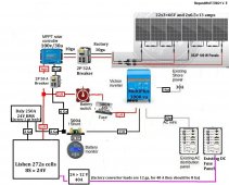
Here is the new drawing

trailer solar wiring diagram_e.jpg
 
Out of curiosity, what are you doing for the 120 volt AC to 12 or 24 votl DC converter that come with your vehicle?

Currently, I just flip the AC to 12 DC converter circuit breaker off whenever I turn on the solar inverter. Now that I'm doing a 12 votl to 24 volt upgrade, I needed to purchase a whole AC to DC converter. To me it looks like the way the multiplus is wired, you don't even need the converter that come with the trailer.
There are two things in the factory design I am not using. For now, the AUX line from the trailer coupler is not being used, and I will be bypassing the factory battery charger. The factory charger would be the wrong voltage, and redundant because I will be using the charger in the inverter. I don't know if I will physically remove the factory charger or leave it in, depends on if it gets in the way of wiring. I believe it is a Progressive 9300 or something like that.
 
Which panel amperage are you referring to? I hadn't heard of such a thing.
Solar panels, the link has examples.

Victron's manual says to use a 300A fuse....no ranges of values, just 300. You are the second person to mention it could be lower.
I'd write/call them and ask then. If they're speccing a 300A fuse that means they expect there can be 300A on it, in which case the wire gauge might be off.

The switch is probably not approved by anyone but Amazon :) https://www.amazon.com/gp/product/B07413JWLD
That's the type I'm warning against. It might work fine, but it might not.
https://www.amazon.com/gp/product/B07413JWLD

Your last point was in regards to the converter. Although the converter is rated at 40A, the wiring on it is 12ga. I intended to use 8ga to the DC panel, but is there a point if the converter's input and output wires are 12ga? Same issue with the BMS. Daly put 2 Ga wire on the 250A BMS. Those are the two instances in which I seem to be undergauged, and both are at the "fault" of the component manufacturer.
Not sure... possibly those ratings are the maximum ratings rather than the continuous ones?

Linking @smoothJoey as he recently talked about how NEC allows 90C THHN for 105C in appliance wiring in the thread referenced earlier, I'm still not exactly sure, but I suspect the difference is how much cooling the wire gets (e.g., if a fan is blowing air across it or something or it can have convective cooling because it's not in a conduit). So, possibly okay in their "appliance", possibly not okay in a conduit wire run (I try not to build close to the edge, don't generally like wires hotter than boiling water, it's okay in the toaster). He might have something additional to add to it.

He also talked about how a 40 amp converter is on the demand side, so 480 watts. But, as they're not 100% efficient they pull more than 480W/24V=20 amps on the supply side, e.g., a 90% efficiency would pull 23 amps).
 
Back
Top