diy solar

diy solar

Custom aluminum battery compression enclosure

Firstascent

Solar Enthusiast
Joined
Mar 7, 2020
Messages
265
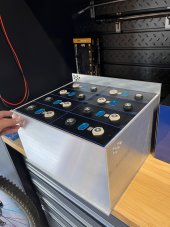
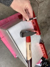
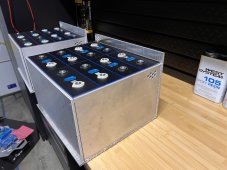
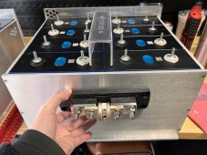
Here’s the start of my compression enclosure for my EVE 280ah cells.
I know it’s still debatable whether to compress these or not, I decided awhile back I was going to compress mine. However recently after seeing how companies such as the various server rack batteries build theirs with no compression, and with warranties makes me second guess. But here I am and they’ll be compressed haha.

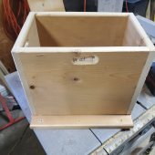
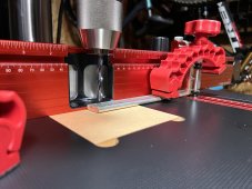
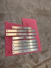
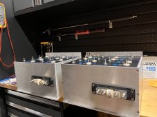
I’ll have two identical enclosures, 1/4” aluminum plates. The bottom and back piece is one solid piece bent at a 90° angle. The two side pieces will be welded in place, and the front piece will be tapped and bolted with multiple m4 screws which will apply the compression. It’s nice and stiff 6061 aluminum.
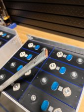
The width is a perfect snug fit for the cells but not necessarily compressing since that isn’t needed on the sides.

And don’t worry, the cells won’t touch the aluminum directly. I’m using 1/8” poron padding on all sides and 1/16” for the bottom.

Unfortunately I don’t know how to weld so I’ll have a local shop weld it next week then can finish the build including cutting my busbars.
 

Attachments

  • A00F44F0-FDE9-4CD5-B1CC-D674D8D18232.jpeg
    A00F44F0-FDE9-4CD5-B1CC-D674D8D18232.jpeg
    151.5 KB · Views: 178
I just made a box from wood. When I put the end on and tightened it closed, it pulled the batteries tight together. You can turn the box upside down and the cells will not fall out.

I would recommend you predrill all the holes and assemble the box before putting cells in so you don't run a screw into a cell.
 

Attachments

  • 20220116_162945.jpg
    20220116_162945.jpg
    166.7 KB · Views: 81
  • 20220116_201802.jpg
    20220116_201802.jpg
    218.7 KB · Views: 80
Oh yeah I’m fully assembling/drilling everything without the batteries. I was just holding up the sides to give an example.

I like how your box has handles, I’m still deciding how I want to do that.

Did you use a router for your cutouts? It looks great btw
 
  • Like
Reactions: NVS
Oh yeah I’m fully assembling/drilling everything without the batteries. I was just holding up the sides to give an example.

I like how your box has handles, I’m still deciding how I want to do that.

Did you use a router for your cutouts? It looks great btw

Yes, I routed all the edges for a smooth finish for the wires. Mine is also going in an RV so I wanted the cells tight in the box to avoid abrasion from the rough roads.
 
Yes, I routed all the edges for a smooth finish for the wires. Mine is also going in an RV so I wanted the cells tight in the box to avoid abrasion from the rough roads.
Sweet, mine is going in an RV as well.
I recently got a small handheld (Milwaukee) router to play with but haven’t used it yet. I also don’t have any bits yet haha, but also suspect I’ll only be able to use it for wood projects not aluminum haha
 
Made some good progress today and yesterday. The sides are now welded on and the front compression plate is now drilled and tapped to the body. Batteries are secured and are not going anywhere.

Busbars are also all cut to length and drilled! Hopefully tomorrow I’ll install the busbars, I’ll be using a small wire brush on a dremel-like tool to clean the terminals before hand.

So excited to finally be close to done with the battery enclosure as this has been holding up my build process haha.
 

Attachments

  • C75C97CA-58C1-4380-9A85-5B6E6F6C6571.jpeg
    C75C97CA-58C1-4380-9A85-5B6E6F6C6571.jpeg
    248.7 KB · Views: 126
  • 1CA8DE97-FA2B-4F23-832B-8804CC59702C.jpeg
    1CA8DE97-FA2B-4F23-832B-8804CC59702C.jpeg
    150.6 KB · Views: 131
  • 5C7F5DFD-E73A-4C9C-847D-20039E60BD5A.jpeg
    5C7F5DFD-E73A-4C9C-847D-20039E60BD5A.jpeg
    269.4 KB · Views: 135
  • 7D73AF10-4CF0-42F8-B739-D7117F44D168.jpeg
    7D73AF10-4CF0-42F8-B739-D7117F44D168.jpeg
    117.5 KB · Views: 130
  • 09B8C4AC-AB98-43B7-AB20-CCC04F85794C.jpeg
    09B8C4AC-AB98-43B7-AB20-CCC04F85794C.jpeg
    243.9 KB · Views: 119
  • D5ABB35E-61D7-445B-BE4B-CF57654B43AB.jpeg
    D5ABB35E-61D7-445B-BE4B-CF57654B43AB.jpeg
    235.3 KB · Views: 120
  • B24A6C10-FFF6-497D-B35E-EC7515AB6EB8.jpeg
    B24A6C10-FFF6-497D-B35E-EC7515AB6EB8.jpeg
    222.9 KB · Views: 124
Stainless M6 studs are now in. To keep them from accidentally bottoming out when I’m tightening the top nut I used a little bit of this silver epoxy compound which is supposed to be very conductive due to the high amounts of silver. This should hold them in place but also not make it impossible to remove later on if I need to for whatever reason.

Last thing I almost forgot about is my Class T fuse location. Im going to direct mount it to the case and attach either a couple inch long cable attaching to be main positive or I may extend the busbar, bend it into a 90° L shape, and attach that directly to the class T fuse.
I think that would be slick but I’ll have to see if I can bend the 1/4” thick busbar cleanly
 

Attachments

  • E6414837-D135-466A-85B1-DEB76FB57DE4.jpeg
    E6414837-D135-466A-85B1-DEB76FB57DE4.jpeg
    195 KB · Views: 97
  • E7409F85-8F1E-4522-BDAC-8AC31932A368.jpeg
    E7409F85-8F1E-4522-BDAC-8AC31932A368.jpeg
    243.8 KB · Views: 81
  • 1C3F24D8-D516-4468-9793-C08703D8194A.jpeg
    1C3F24D8-D516-4468-9793-C08703D8194A.jpeg
    181.5 KB · Views: 95
  • CD541879-2AA8-41EC-9EF5-9223210340A3.jpeg
    CD541879-2AA8-41EC-9EF5-9223210340A3.jpeg
    284.2 KB · Views: 98
Class T Fuse holders are now directly mounted (drilled and tapped with M6 bolts) to the enclosure front face. They will attach to the mains with a ~3” wire.
The M6 bolts are 12mm in length and end at the end of the front faceplate, so there is no chance of them sticking past the padding and into the cells.

I know, not AS good as directly mounted to the positive busbar but I’m ok with this.
 

Attachments

  • B9EA1593-1F8A-4C80-8DB6-0FF0102E21D2.jpeg
    B9EA1593-1F8A-4C80-8DB6-0FF0102E21D2.jpeg
    231.8 KB · Views: 74
Busbars for one of the batteries are all heatshrinked and ready. I don’t have enough of this size heat shrink for the other Busbars so ordered another 4’ stick. But for now I can get these fully installed. First I’ll apply MG Chemicals 847 conductive paste on the cell terminals before placing the Busbars. D942B7E7-E3E9-465C-B8F9-1477E34EA2CE.jpeg
 
At risk of starting a fire. I’ve used that exact paste and applying it too thick on high current buss bars has been very problematic, at least for us. Best to monitor those joints for excessive heat / resistance after some time under high load. Maybe you’ll have better luck. Nice work by the way!
 
At risk of starting a fire. I’ve used that exact paste and applying it too thick on high current buss bars has been very problematic, at least for us. Best to monitor those joints for excessive heat / resistance after some time under high load. Maybe you’ll have better luck. Nice work by the way!
Thank you! and very interesting, I've currently only heard amazing things about MG 847, even on various threads from this site. This is the first I've heard of that type of issue. Did you notice it right away during high loads?

Once I connect everything, the first thing I'll be doing is charging them back up to 100% at the max setting the Victron gear can do which is about 110-120Amps. The cell monitors give me temps of each cell, and I have a fancy Fluke infrared camera. So I'll have a very clear picture on how it reacts under this heavy load.

I'm sure you checked, but all your busbars were tight, fastened down OK right? loose busbars could cause heat issues. like I said I'm sure you checked but worth asking so I'm not assuming :) Also, what did you end up doing, wiping it off entirely?
With my Batrium BMS I can set the cell temperature alarm for whatever. so I may set it lower than usual at first to monitor it more closely as well after everything is finalized.
 
Ok, here goes and I hope your thread doesn’t go sideways. For a while my electronics company was building custom switch gear for utilities and subways. All high voltage and currents, and tight controls over them. We had and used FLIR infrared cameras all the time to spot issues, all Fluke and Tektronics test equipment. All bars torqued with high end NIST calibrated and certed torq wrenches.

After a period of time, (nothing that could be scheduled around), just odd ball amounts of time would pass and we’d start seeing excessive heat on lugs and bars where excessive amounts of paste was applied. That stuff is great at stopping corrosion but it had measurable resistance. More resistance than a clean tight metal junction would have without. Engineering believed that when the paste was applied too thickly to a clean NEW joint, that never squeezed out enough during torquing but eventually did causing a loose joint, and further that it did have resistance itself. Our thoughts were; it was great for connections that generally had crappy finishes pitting etc but that a clean, properly finished surfaces performed much better over time without it. The final outcome was newer equipment with quality bars and lugs no longer had it applied at install (and issues vaporized), older or crappier connections had it applied very thinly in amounts that would only fill pores and pits in, (adding current pathways that was not there). The final determination was, why add something with more resistance to the joint than it had without. There were better ways we found to solve water and moisture corrosion from occurring without causing the problems we were seeing. The thing we had great success with was spraying lug and bar connections after torquing with 100% food grade high content pure silicone, that made a huge dent on issues in the damp subways. For old crappy pitted connections we did “seal” the joints on the edges with the paste after a thin layer in the joint . Anyway that’s our experience. Our stuff was very hard to get back to down in the tunnels so we tried to do what we could to avoid anything that would require us to go back.. frankly it’s nasty down there. Best of luck with your project.
 
I can’t tell what I’m looking at here. Could you provide some detail? And classy build.
haha no problem.

the first photo shows me applying MG 847 (the black paste) on to the top of the cell terminals. Only half of the cell terminals have it applied in that photo. so you can see some appear black and some are still the raw aluminum silver color.

The second photo is the top-down view of the busbars all installed. The little circuit boards on each cell are for my BMS (Batrium) They will monitor temperature and voltage of each cell and can balance them by dissipating heat according to my settings. The cell monitors are called Blockmon's from Batrium.

Hope that helps! If not, happy to clarify or answer any further questions. and thanks or the compliment!
 
Ok, here goes and I hope your thread doesn’t go sideways. For a while my electronics company was building custom switch gear for utilities and subways. All high voltage and currents, and tight controls over them. We had and used FLIR infrared cameras all the time to spot issues, all Fluke and Tektronics test equipment. All bars torqued with high end NIST calibrated and certed torq wrenches.

After a period of time, (nothing that could be scheduled around), just odd ball amounts of time would pass and we’d start seeing excessive heat on lugs and bars where excessive amounts of paste was applied. That stuff is great at stopping corrosion but it had measurable resistance. More resistance than a clean tight metal junction would have without. Engineering believed that when the paste was applied too thickly to a clean NEW joint, that never squeezed out enough during torquing but eventually did causing a loose joint, and further that it did have resistance itself. Our thoughts were; it was great for connections that generally had crappy finishes pitting etc but that a clean, properly finished surfaces performed much better over time without it. The final outcome was newer equipment with quality bars and lugs no longer had it applied at install (and issues vaporized), older or crappier connections had it applied very thinly in amounts that would only fill pores and pits in, (adding current pathways that was not there). The final determination was, why add something with more resistance to the joint than it had without. There were better ways we found to solve water and moisture corrosion from occurring without causing the problems we were seeing. The thing we had great success with was spraying lug and bar connections after torquing with 100% food grade high content pure silicone, that made a huge dent on issues in the damp subways. For old crappy pitted connections we did “seal” the joints on the edges with the paste after a thin layer in the joint . Anyway that’s our experience. Our stuff was very hard to get back to down in the tunnels so we tried to do what we could to avoid anything that would require us to go back.. frankly it’s nasty down there. Best of luck with your project.
oh man, thanks for the detailed info! I really appreciate it! I have a lot of fun test gear (such as my fluke infrared camera) but a meter to measure that low of resistance to compare with/without I do not have. However, there was a user on here recently that posted up a test he did, where he measured the resistance of two busbars connected directly to each other, and then two connected with MG 847. the ones with MG 847 had a lower resistance.
Your experience seems to be quite the opposite however. I'm very intrigued by this and wish I had the tools to do more testing. and now it's going to be in the back of my head haha. I may remove the bus bars and just make sure I have a more thin layer on, but I'll still leave it there.
Actually, I may also call MG Chemicals to get their input on application thickness to see if they have any thoughts. Their instructions do not say anything about how much to apply.
I definitely see your point about bad/pitted connections and can see where it would be a benefit "filling in the gaps".

Hmmm, lots to think about here. thanks!

[edit] here is the thread where the user did the 847 test
 
Back
Top