diy solar

diy solar

Daly 24V 8S Initiation and Software

Zwy

Solar Wizard
Joined
Jan 3, 2021
Messages
5,788
Location
Timbuktu, IA
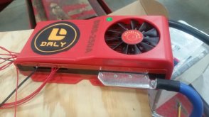
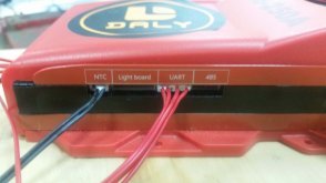
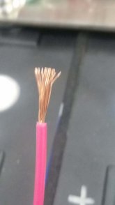
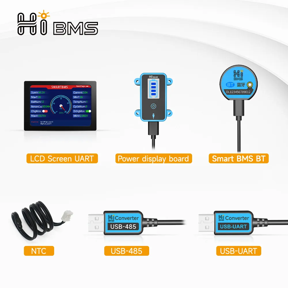
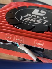
I'm going to consolidate some of the Daly Smart BMS questions into one thread concerning initialization and parameter setting, some of it I found here in odds and ends, some I discovered on my own. First off, thanks to those who pioneered ahead of me and found ways to get these to work. I purchased a Daly 24V 8S BMS off AliExpress Daly Factory Store. Shipping was quick, less than 2 weeks. I also purchased the Bluetooth module, the LCD display, the 485 cable and the UART/USB cable. I did not purchase the Light Board. After hooking to my fully charged top balanced bank, I could not get initialization and turn on. NTC was plugged in as was LCD display. Searched here among many threads, tried shorting P- to B-, ohmmeter trick, everything short taking a hammer to it. Balance leads had been checked several times, I had it wired correctly. Tried drawing a load, didn't work either. I had full battery voltage at P- until a load was put on it, then it dropped to about 6v. I finally came across a few threads about shorting the 2 pins together on older Smart BMS's, my BMS didn't have those ports. I looked at the BMS manuals found here in Resources, some of the info applies but much doesn't. All I have is what is pictured. I had one final try, I took a piece of wire, stripped the end, spread the wires out and made a key. I took the key and dragged it across the terminals inside the Light Board port and it turned on. Success finally.

Next came setting parameters. I had already downloaded the PC version, however the Malware software I have on my laptops indicated the Daly PC software is infected with Malware and prevented any operation of the software. I tried using an old Win XP laptop I have laying around, it needs a .NET program to work. So much for that idea. I abandoned any thought of a PC hookup. Next, I tried using my Chromebook and the Android app address listed on the "manual" that came with the BMS. This has Huawei listed in the link address and can be found in the resources here. Don't waste your time, you won't get it downloaded. I decided to try my phone with BT app. I did find you can unplug the display and hook up the BT connection without disconnecting power. It would have been nice to run both at the same time, either thru split ports or a splitter. I did go to Google Play and downloaded the app here. https://play.google.com/store/apps/details?id=com.inuker.bluetooth.daliy This one works and later I downloaded it to my Chromebook and it works on it also.

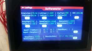
I did reinstall the display and went back to parameter settings again and tried to change settings there. I wasn't successful the first time, I kept hitting Set but nothing would happen the first time. The second attempt I hit the actual reading and it then asked for the usual password of 123456. After that input your desired setting, then hit Set. Works great. Be sure when you are in parameter settings to enter Zero Current Calibration with no draw on the battery. This will help with accuracy on SOC and Ah remaining.

It's been a time consuming process figuring much of this out plus scouring various threads here. Hopefully those who have trouble with initialization and parameter setting find this thread and it helps them. In the process, I learned much about the BMS and if I need to troubleshoot it.
 

Attachments

  • Daly 250A Smart BMS.jpg
    Daly 250A Smart BMS.jpg
    49.3 KB · Views: 185
  • Daly Smart BMS ports.jpg
    Daly Smart BMS ports.jpg
    40.4 KB · Views: 184
  • Daly Smart BMS key.jpg
    Daly Smart BMS key.jpg
    56 KB · Views: 195
  • Daly Smart BMS parameter setting.jpg
    Daly Smart BMS parameter setting.jpg
    47 KB · Views: 182
Indeed, ignore the Daly directions for the Android app, you don't want to visit the Huawei store.
Just search "smart bms" on the Google play store, should come up with "SMART BMS" by "DalyBMS". You can also search on this forum, people have uploaded newer versions of the PC software (which is much more configurable).

I don't see a picture of the side where the pins you should short are located (note this is for a 12v, 4 cell "smart" BMS). Note that everything should be connected first, and plug in the balance/voltage leads last, then short these two pins.

Here are pictures of my 4 cell Daly for reference.
Daly_USB_Reset.jpg
Daly_Bluetooth_Temperature.jpg

My 24v Daly (no fan, but 250 amps) doesn't have these pins like the 12v model (also 250 amp, no fan). They sent me a different lightboard that has an "activation" button. I might take it apart and see what they are doing, it's just a USB interface, not sure if the button is just a switch, or sends a signal through USB. Certainly it has more pins than is required for a USB connection.
Daly_24v_lightboard.jpg
 
Last edited:
OK, took apart my "lightboard" for my Daly 8 cell, "smart" BMS (no fan), and as I suspected the switch is directly connected to two pins on the connector that plugs into the BMS. It is normally open, and when depressed is closed until released.
Daly_24v_lightboard_connector.jpg

The other side of the lightboard has no circuitry, just a few circuit lines, can't even get to the pins for the "USB" connector. Looks like there is indeed a USB interface, but they use lots of other lines (I'm guessing individual lines to light up the bar graph display). My guess (not being willing to destroy it) is that pin 1 is ground (start numbering at 1 from the top of the above picture), pins 2 and 4 are transmit and receive for USB, and then 5, 6, 7, and 8 are to light up the individual segments of the "gauge" (note I just ohm'd these out, and indeed each individual line 5-8 goes to a separate resistor you can see on the front next to the switch). That would mean short pin 3 to ground (pin 1, I'm guessing ground just because it's black) to reset or wake the BMS. I hope that helps people, no reason Daly should make you guess this stuff.

Daly_24v_lightboard_circuit.jpg

Daly_24v_lightboard_back.jpg

For completeness, it is a Daly R32W-FL08.

Daly_24v_Model.jpg

And a picture of the connector on the BMS.

Daly_24v_connector_BMS.jpg
 
Last edited:
OK, took apart my "lightboard" for my Daly 8 cell, "smart" BMS (no fan), and as I suspected the switch is directly connected to two pins on the connector that plugs into the BMS. It is normally open, and when depressed is closed until released.
View attachment 38005

The other side of the lightboard has no circuitry, just a few circuit lines, can't even get to the pins for the "USB" connector. Looks like there is indeed a USB interface, but they use lots of other lines (I'm guessing individual lines to light up the bar graph display). My guess (not being willing to destroy it) is that pin 1 is ground (start numbering at 1 from the top of the above picture), pins 2 and 4 are transmit and receive for USB, and then 5, 6, 7, and 8 are to light up the individual segments of the "gauge" (note I just ohm'd these out, and indeed each individual line 5-8 goes to a separate resistor you can see on the front next to the switch). That would mean short pin 3 to ground (pin 1, I'm guessing ground just because it's black) to reset or wake the BMS. I hope that helps people, no reason Daly should make you guess this stuff.

View attachment 38006

View attachment 38010

For completeness, it is a Daly R32W-FL08.

View attachment 38018

And a picture of the connector on the BMS.

View attachment 38019
I looked at my 250A with fan but can't find a model number. Mine is the latest style with the raised fan. Even looking here I don't get a model number. https://www.aliexpress.com/item/4001316243469.html?spm=a2g0s.9042311.0.0.7a584c4dqFPDzO If I ordered another one, I would order the UART/BT/Fan model and drop the 485. plus the touchscreen, BT module and light board as the light board is only $4.16 USD. This would allow use of touchscreen and BT at the same time. Light board socket is just like yours, 8 pin. I believe I went to right side of socket for turn on which looks to be the pins you labeled as 1 and 3. If you press the button, does it shut down the BMS? I'm impressed thus far with this BMS once I got it up and running. Low temp charging cutoff works also.
 
Looked at the manual here, part 2 and yes, the pinout for light board connector shows pin 1 as ground and pin 3 as S1 which is probably the switch.
 
Looked at the manual here, part 2 and yes, the pinout for light board connector shows pin 1 as ground and pin 3 as S1 which is probably the switch.
Can you provide a link to the manual? I certainly never found any documents on pinouts!

I've found most things can be ordered, if they work or not might be the question, I'm not sure Daly is the actual manufacturer.

 
Can you provide a link to the manual? I certainly never found any documents on pinouts!

I've found most things can be ordered, if they work or not might be the question, I'm not sure Daly is the actual manufacturer.

My bad, I thought I linked it. https://diysolarforum.com/resources/daly-smart-bms-manual-and-documentation.48/ Hit download button top right, then Part 2.
 
Can you provide a link to the manual? I certainly never found any documents on pinouts!

I've found most things can be ordered, if they work or not might be the question, I'm not sure Daly is the actual manufacturer.

If you hit the button, does it shut the BMS down? I've been tempted to fan it with my wire but I've been busy with capacity testing and recharging.
 
If the bluetooth shuts down or if it sees perhaps a cell voltage fault, does the Daly BMS shut off? IE, no battery protection and no power until it is reset? Or would it reset automatically?

Does anyone have a line on the tiny two pin connector or possibly one made up? I would like to install a reset /on-off on the daly 100A 4s smart BMS. Or know where to buy it?

Here you go:


I could probably send you one if you like.

It is NOT an on/off switch, it simply tells the BMS to wake up the bluetooth. If you want to turn the BMS off, disconnect the balance leads, reconnect to turn on.
 
Last edited:
If the bluetooth shuts down or if it sees perhaps a cell voltage fault, does the Daly BMS shut off? IE, no battery protection and no power until it is reset? Or would it reset automatically?

If bluetooth shuts down, the BMS still works. It (shutting down bluetooth) is an energy saving feature, no need transmitting 24 hours a day. It's like shutting off the lights in a room nobody has been in for hours, it doesn't mean the power grid died.
If it sees high cell voltage limit, it will stop charging, but not discharging.
If it sees low cell voltage limit, it will stop discharge, but not charge.
If it sees low temperature, it will stop charge ability until it detects a temperature above the set point.

Daly has problems, and is wildly inaccurate with SOC and current measurements, but basic BMS functions all seem to work fine on mine, your mileage may vary.
 
If the bluetooth goes down, is there any way to reactivate it besides shorting those two pins via a momentary switch or whatever? Reason n being is I'm packaging these batteries in ABS boxes and will be sealed to the consumer. So, perhaps if one cannot activate it without disassembling the batterypack to get to the BMS, that switch may be an ellegant solution. Additionally, does the shorting or pins turn off the bluettoth.. Duh, I can test this out on my bench...... Never mind.
If charging or discharging occurs, the BT should turn back on, just like the LED display. This is to eliminate standby current draw. As for a "switch", Daly does sell a light board which has a few LED's to indicate power level and the switch to short pins 1 & 3. You could build a harness for this purpose, I just use a piece of wire with the strands spread out in a fan and brush it across the pins on the right side of the light board socket. I only had to do this upon initiation when first installing the BMS. I always unhook balance leads first to shut down the BMS, then B-
 
Great information. I am building battery bank (24v@120amp, LIfepo4) to use in my boat with a trolling motor.
I have the Daly 80 amp smart BMS. I have tried wiring the pins 1 and 3, it does turn on the Bluetooth module.
I would like to buy the lightboard, but I am not going to wait more than a month for it to arrive. I will try to make the
lightboard with some leds and resisters.

Paulo from Azores
 
Trying to avoid having to dig thru an engine compartment to get to the battery and turn the bluetooth on or off. How much current could it draw? Now, I have read on how to keep the system/bluetooth on by changing "sleep waiting time" to 15300. I like to keep a close eye on my power systems so I'm hoping installing a momentary switch on those pins is all I need. Now, on my test bench, a newly installed BMS did not have the bluetooth activated and on a 14V pack P- to + was 9.8V. I shorted the two pins (two pins on my bms) and bluetooth activated and the voltage across P- was now normal, 14V. I am not 100% sure this is normal?
Yes, it is normal (if normal means mine exhibits the same behavior).
 
I can connect to my Daly (4S 250A) via BT but it doesn’t display any info.
I’ve also read it’s worth paying the $5 for pro version of the Smart BMS app, but can’t find it?
 
PC, Android or IOS?
I was trying to connect via BT to IOS (iPhone 11 pro). Seems I had the wrong port - I had the BT cable plugged into the unlabelled port. It powered up the dongle but didn’t share any data. Have now plugged into the UART port and it works, including updating almost all settings. Won’t let me update reference Voltage or SOC though, but will have another look this morning.
so why was I using the unlabelled port.... thought I read somewhere that others were using it, and that people could use BT and UART to PC at the same time.
Daly makes many different models, but both my 12v and 24v models allow bluetooth and USB connection simultaneously.

On my 12v model, the USB connection is labeled "monitor".
 
Google translate says the Chinese characters says ‘host computer’. 3 pins- wonder if that’s the PC connection.
 

Attachments

  • 155E1FFB-988A-4AA7-B781-D2291BB472B8.jpeg
    155E1FFB-988A-4AA7-B781-D2291BB472B8.jpeg
    305.6 KB · Views: 36
Google translate says the Chinese characters says ‘host computer’. 3 pins- wonder if that’s the PC connection.
Mine has it on the top with "monitor". The connector with the Chinese writing doesn't exist on mine. Daly needs better docs and to standardize.
 
I was trying to connect via BT to IOS (iPhone 11 pro). Seems I had the wrong port - I had the BT cable plugged into the unlabelled port. It powered up the dongle but didn’t share any data. Have now plugged into the UART port and it works, including updating almost all settings. Won’t let me update reference Voltage or SOC though, but will have another look this morning.

If you run all the way down to cutoff voltage, then charge back up, SOC should update itself.
 
Back
Top