Dhopewell
New Member
- Joined
- Jul 3, 2020
- Messages
- 69
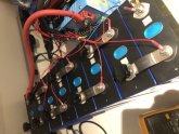
I had a difficult experience with the setup. The wire loom comes with 22 gauge or smaller mostly identical wires, and step 1 was to crimp on ring terminals. I considered making them longer, and wish I had. Step 2 was to attach them out of order, and test them and fix them, making critical error of testing the red battery sensor leads to the main negative pole of the battery because the plug was way too small to touch two meter leads to. Step 3 was to check and recheck for correct b+ and go through start up procedure of B-, then leads, then P- to the load, which is a big inverter, 3kw of low frequency Iron Age engineering. Step 4 was to fail, reverse the setup wiring and try again. Several times. Yes, there was the rated voltage at P-, then no to current through load. More steps repeated, over and over several hours otherwise used for work and fun.
What was the problem?
- it was not the hulking 3kw inverter with big sparky caps
- it was not miswiring
- it was not a problem with the Bms
- it was a problem with Daly’s fragmentary documentation
- it was a problem with the black wire ring terminal, which showed continuity in my hand but lost it when cranked onto the terminal (well below the 8N/m allowed torque of the 280s). I believe this was what started the problem
- it was not a problem with the SOC display I put in the light board slot, and which by lighting up encouraged me to continue
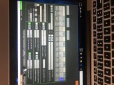
- it was not a problem with making topbms run. It recognized the port and displayed the incoming data as soon as there was some
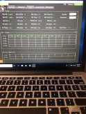
- Finally it was the solution in the topbms software a handy switch called “reset bms”. When I did this the bms actually passed current.
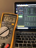
Did you know that inverter caps hold enough energy to power startup for about 7 secs. Now I do. The mysterious voltages people are getting connecting to inverters when the bms is not active is from the caps.
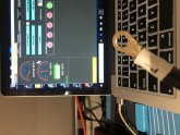
Finally the bms worked. The inverter came on and it stayed on. Cell voltages on display, coloumbmeter running, and parameters to be set and saved in a config file. It was like Christmas
If there’s any interest I’ll run through tests on request. Topbms has a parameter for low voltage charge cutoff. I’m going to find out what happens when it’s exceeded.
What was the problem?
- it was not the hulking 3kw inverter with big sparky caps
- it was not miswiring
- it was not a problem with the Bms
- it was a problem with Daly’s fragmentary documentation
- it was a problem with the black wire ring terminal, which showed continuity in my hand but lost it when cranked onto the terminal (well below the 8N/m allowed torque of the 280s). I believe this was what started the problem
- it was not a problem with the SOC display I put in the light board slot, and which by lighting up encouraged me to continue
- it was not a problem with making topbms run. It recognized the port and displayed the incoming data as soon as there was some
- Finally it was the solution in the topbms software a handy switch called “reset bms”. When I did this the bms actually passed current.
Did you know that inverter caps hold enough energy to power startup for about 7 secs. Now I do. The mysterious voltages people are getting connecting to inverters when the bms is not active is from the caps.
Finally the bms worked. The inverter came on and it stayed on. Cell voltages on display, coloumbmeter running, and parameters to be set and saved in a config file. It was like Christmas
If there’s any interest I’ll run through tests on request. Topbms has a parameter for low voltage charge cutoff. I’m going to find out what happens when it’s exceeded.