diy solar

diy solar

DALY BMS, Charge and discharge at the same time?

Bumblebee

New Member
Joined
Oct 18, 2020
Messages
9
Hi,
I was wondering if anyone had done this before? For example in a mobile vehicle application, you might want to still be running your motors while charging the system so that it can drive away once it reaches a certain threshold. Does anyone know if DALY BMS support the ability to simultaneously charge and discharge without having to lose power to loads while charging?

Thanks for any help

Batteries NEVER charge and discharge at the same time. There is always a net discharge, charge or 0A. If it's doing "both" as you suspect, one subtracts from the other to result in one, the other or nothing.

Chargers work to maintain the programmed voltage. If that voltage drops due to a load, the charger increases output to maintain the voltage. If the charger can power the loads, there is no or negligible flow to/from the battery. If the charger can't power the loads, then the battery discharges while the charger outputs its max to try and raise the battery voltage.

Can you simultaneously charge and discharge a mobile power system? Youbetcha. It just has nothing to do with the BMS. BMS is just a safety device that protects the battery when operated outside of specification.
Hi, and sorry in advance for my english.
I'm coming back on this subject cause I'm not sure understanding the answer.
I just buy a 3kw solar system with apsystem micro inverter.
I plan to build a 7s li-ion battery, and charge it with my production surplus, with this commun port BMS:
This battery with be connected to a 1000w pure sine ware inverter, to power my office room.
so several question:
Is that possible to charge my 7s battery, with a classic ac to dc charger during day when I over product, and simultaneously use my computer connected to the inverter? Or do I have to had something in my assembly, like a solar charge controler to "separate" my charger, my battery and my load?
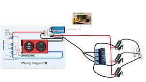
Is that possible to connect, for exemple, several 29v 2A, AC to DC charger to some arduino/esp32 relais bar, as that:
and open each relais accordingly to the production surplus (1 relais open when 60W surplus, 2 relais when 120W surplus...)

thanks for any help
 
Last edited:
Is that possible to charge my 7s battery, with a classic ac to dc charger during day when I over product, and simultaneously use my computer connected to the inverter?
Yes. Any “surplus” solar just goes to the load. As noted above this is how all batteries work.
 
That was to be sure.
Is my scheme making sense or not?
I want to open relais accordindly to my production surplus. 1 for 60W surplus, 2 for 120W.... If all my AC/DC charger are the same voltage (29.4V), does my scheme wiring increase global current of the charger part, and will charge my battery at 2A for 1 relais, 4A for 2 relais, or do will have problem?
Thanks
 

Attachments

  • ChargerScheme.jpg
    ChargerScheme.jpg
    168.2 KB · Views: 12
Where is your solar in all of this? Why are you controlling the chargers with relays? Not really sure I understand what you are trying to accomplish.
 
My PV will be connected to APSystem micro controller, so I will have AC at the output of micro controllers, and this will be connected to my home electric panel, right?So my Solar is "before" the multi-socket adaptor and I don't draw it.

So surplus of my panel can't go directly into my battery. I have to transform AC of my house to DC, then charge my battery.

I already have CT clamps and I plan to calculate production and consumption, that give surplus , and use relais to open 1,2 or more little DC charger to charge my battery if I have surplus, but not charging more than my surplus (Hence the idea of using several little dc charger, to have 60W of "modulation" on my surplus) And Use this battery in my shelter ,on a line that is separate of the house lines.

I also plan to put my water heater on a AC dimmer, to use my surplus on priority, before charging this battery.

Hope my answer will help to understand my ecosystem.
 
Clarification:

You can't charge and discharge a battery at the same time. One or the other is happening, not both. Current will only flow one way into or out of the battery.

HOWEVER, you can apply charge to a system and draw loads from a system simultaneously.

If you have 10A of charge current from all sources and 20A of loads, the battery is DIScharging the 10A to make up for what the chargers aren't supplying.
 
If you have 10A of charge current from all sources and 20A of loads, the battery is DIScharging the 10A to make up for what the chargers aren't supplying.
I understand that charge and discharge don't append at the same time. My question was more can I draw a loads when my DC charger are open. And I now have the answer, thanks.
But what about my multi Small DC charger driven by arduino/esp32 relais? is my idea can work? Is my wiring correct.?
 
I still don't understand why you are trying to charge the batteries from AC only to use the battery to run an inverter. Where is the AC for the chargers coming from? And why use relays instead of just using a charger designed for lifepo4? It will only draw the amount of current needed. No need for relays etc.
 
Sorry for my english, it's a bit hard to explain what's in my mind . Is my scheme more comprehensive?
My solar will be AC current and connected to my house electricity meter.
My battery will be made as a 7S 18650 Li-ion Battery.
my idea is to use ct clamp to calculate my surplus at any time, and manage the amout of amps that I can send to the battery.
If my PV produce 800, my house consume 740, I have 60W surplus, I can open 1 relais, send 2 Amps 29.7V to my battery
If my PV produce 800, my house consume 680, I have 120W surplus, I can open 2 relais, send 4 Amps 29.7V to my battery.
The idea is to charge the battery without the grid electricity, and create a line to a place without electricity actually.
You talk about a charger designed for lifepo4. How can I manage how many amps I send to the battery to avoid grid electricity (and bill)?Is it automaticaly draw only surplus?
I didn't choose this option mainly for price. the APstorage els-5k is the price of my entire solar system. If I can do the same with several 10Euros DC chargers and a 1000 or 2000w pure sine wave inverter, Isn't it a good idea?

thank you for the effort to try to understand me :LOL:
 

Attachments

  • ChargerScheme.jpg
    ChargerScheme.jpg
    213.7 KB · Views: 5
Last edited:
Additionnaly, can I connect the output of the inverter back to my house electricity panel and start it at night when I want to use battery energy?
Is my idea even make sense for anyone?
What are solutions to store surplus in 7s 18650 li-ion battery, without spend thousands euros?
 
Whenever this discussion comes up I wonder if a DC charge source going into a circuit with an AC inverter load could create a 60hz ripple where the battery is alternative between charge and discharge 60 times a second. Not that it really matters because the net will be power flow in one direction, and the caps on the inverter might smooth it out into true one direction power flow. Just seems like an interesting caveat to the statement that a battery never charges and discharges simultaneously.
 
Is it automaticaly draw only surplus?
More or less yes, it's a double conversion system. The AC adapters or chargers can only pass through energy that is being absorbed either by the loads or battery. Energy cannot get lost.

They need to be designed not to apply too high of a voltage. This can be achieved with chargers that have intelligent voltage control, adjustable voltage power supplies, or fixed power supplies that output the desired voltage.
 
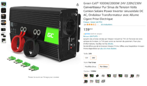
my final inverter will be this kind of inverter.It's pretty cheap. How cost charger designed for lifepo4?
I will power only a line separated from my house electric lines, like a backup line, on 230v AC for exemple, only using the battery.
Do I need more than this cheap inverter to use battery energy on 230v AC device?
Do I need to spend more than several cheap AC-DC charger to charge my battery by a BMS? Isn't the BMS will be the pass-through element of my scheme?
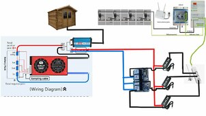
Does my wiring will work at all?

Thanks and sorry to insist, I don't understand why my idea isn't good


1707318917943.png
 
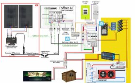
I complete my scheme a bit, try to explain what I have in mind.
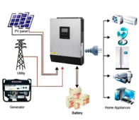
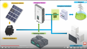
do you think that better to take a solar inverteras this one (https://www.vevor.fr/onduleurs-sola...Qr47iVUuLu1SZ59X5AWSBfv6cRROvntxoCyWwQAvD_BwE), even if there is no solar coming in?( as my pv will be connected to micro-inverters, I can't connect them to solar inverter)
As this second scheme, but with no PV connected, and grid + AC-DC charger (generator in the scheme) as input of the solar inverters?
1707419518191.png
 

Attachments

  • Schema Electrique- Installation complete- V1-02.jpg
    Schema Electrique- Installation complete- V1-02.jpg
    276.4 KB · Views: 5
Somethings like that is more conventional?
Do someone know if every hybride inverters work without PV plugged?
Do someone have reference for small inverters that can work on this scheme and doesn't cost 800e?
Thanks
1707423467988.png
 
I'm still trying to understand why you are trying to use 4 relay controlled chargers. Any off the shelf lifepo4 charger will work fine. The battery will only draw as much current as it needs, so no need to "stage" individual chargers.
 
What do you meen by "any off the shelf lifepo4 charger will work fine"? Can you send me a product reference for exemple?Doesn't this kind of charger (inverter) need to be AC coupled to know how many energy can be send to the battery?
How does "any off the shelf lifepo4 charger" know my surplus and only charge this amount of energy in the battery if PV are not connected to it?
I try to use 4 relay controlled chargers to limit amps available to charge to battery (2a for 1 charger, 4A for 2 chargers...) and so limit charge to exact pv production surplus.
 
Back
Top