diy solar

diy solar

Daly BMS disaster, PLEASE HELP!

hubieg

New Member
Joined
Feb 5, 2021
Messages
25
Greetings,
I have a 32 cell 200 ah LiFePo4 battery pack I just installed along with an Epever XTRA MPPT and 3000w inverter.

The batteries are wired 8 in series, with 4 packs of 8 in parallel for my 24 volt. I have 4x Daly 8S 24V 150A "R32U-GB04" BMS on each pack. The problem started with 1 of the 4 not "waking up". Another of the 4 is "buzzing". I shorted pins 1-3 on the non-working one and it came alive but only as long as I keep the pins shorted.

Long story short, I was finally told by Daly that these units CANNOT be run in parallel! Now I am at a loss for what to do to monitor my batteries. It seems nobody makes a 32S 24v BMS. ANY AND ALL HELP would be appreciated on how to proceed from here.
 
well, if daly says they cannot be run in parallel, you are stuck there. It would have been helpful if they explain "why"...
I certainly could understand the current surge from connecting battery packs with significantly different voltages which would result in a bms disconnect. If the cells have a similiar voltage (say within 50mv), and are configured the same, the voltage differences would never result in a significant current surge. Hmm what bms does battleborn or bigbattery use in their batteries??
 
I'm running two Daly BMS in parallel on my golf cart. At least I'm pretty sure I am, lol. This post has me wondering and I plan to make sure that both batteries are "on" when I get home. These are the "dumb" BMS, since I'm still waiting on my Bluetooth versions to get here from China.
 
I'm running two Daly BMS in parallel on my golf cart. At least I'm pretty sure I am, lol. This post has me wondering and I plan to make sure that both batteries are "on" when I get home. These are the "dumb" BMS, since I'm still waiting on my Bluetooth versions to get here from China.
Check them REALLY good! Out of the 4, one was dead. It would "wake up" as soon as I jumped pins 1-3 on "lightboard" (as others here pointed out) it worked but then dropped as soon as i removed the jumper. The other one was "buzzing" with current draw. the other 2 were quiet.
 
Check them REALLY good! Out of the 4, one was dead. It would "wake up" as soon as I jumped pins 1-3 on "lightboard" (as others here pointed out) it worked but then dropped as soon as i removed the jumper. The other one was "buzzing" with current draw. the other 2 were quiet.
Did you run a test on each individual pack and check capacity? You could have one cell in a pack causing shutdown.

As for the buzzing, sounds more like a connection problem.

I don't know why you couldn't run in parallel. Considering your inverter is 3kw, I would have gone with Overkill on each bank.
 
Are you running 4 parallel to a main busbar? Dont know why it woyldnt work.
And you said 32s. Is that a mistake?
I would recommend REC , but it's kinda pricy and their manual sucks.
But so far it has run well , and controls the SMA charging flawless.
 
Greetings,
I have a 32 cell 200 ah LiFePo4 battery pack I just installed along with an Epever XTRA MPPT and 3000w inverter.

The batteries are wired 8 in series, with 4 packs of 8 in parallel for my 24 volt. I have 4x Daly 8S 24V 150A "R32U-GB04" BMS on each pack. The problem started with 1 of the 4 not "waking up". Another of the 4 is "buzzing". I shorted pins 1-3 on the non-working one and it came alive but only as long as I keep the pins shorted.

Long story short, I was finally told by Daly that these units CANNOT be run in parallel! Now I am at a loss for what to do to monitor my batteries. It seems nobody makes a 32S 24v BMS. ANY AND ALL HELP would be appreciated on how to proceed from here.

I think that would be "8S 24V BMS". "32s" would be nominal 96V. I haven't heard of a single BMS designed for multiple parallel strings.

24V, 150A is 3600W. Maybe enough to run a 3000W inverter but around max current through the BMS, not derated for margin. Wouldn't support surge, unless the BMS allows surge.

If you rewire your 8s4p (four separate 24V batteries) as 4p8s (each group of four cells wired in parallel), then a single BMS would manage it.

If other people have in fact managed to run two of these BMS in parallel, and maybe you have one bad BMS, you could do two 2p8s batteries, each with its own BMS.

Having the single BMS control a contactor or SSR would be one way to overcome current limitation of the BMS. It wouldn't have measurement of charge/discharge current then, so wouldn't know SOC. I think if you keep charge current going through BMS that will let it do low-temperature disconnect of charging.
 
Thanks for the feedback so far! Below is a discussion with Daly "Our bms can't support use in parallel." I even tried to make sure nothing was lost in the translation.
-------------------------------------------------------------------------
07:18

Our bms can't support use in parallel.
Alibaba Translation

08:20

they are on 4 separate battery packs

all with ground connected to inverter

is this what you consider "parallel"?

08:32

yes.each battery pack connect with one bms,then 4 bms connect in parallel.
-------------------------------------------------------------------------

As for 32S, yes this was a mistake. they are 24v 8S 150A units. The "buzzing" one would only do it at high charge or discharge on one unit. If I fiddle with one of the B or P leads it would lessen but not go away.

As for the "dead" one, I swapped the unit itself directly with a working on. Same thing. Jumping the 1-3 wires was the only thing that made it work. Even then it wouldnt stay working and I couldnt establish RS485 communication with it. I did this in addition to checking every lead at the plug header.
 
I think that would be "8S 24V BMS". "32s" would be nominal 96V. I haven't heard of a single BMS designed for multiple parallel strings.

24V, 150A is 3600W. Maybe enough to run a 3000W inverter but around max current through the BMS, not derated for margin. Wouldn't support surge, unless the BMS allows surge.

If you rewire your 8s4p (four separate 24V batteries) as 4p8s (each group of four cells wired in parallel), then a single BMS would manage it.

If other people have in fact managed to run two of these BMS in parallel, and maybe you have one bad BMS, you could do two 2p8s batteries, each with its own BMS.

Having the single BMS control a contactor or SSR would be one way to overcome current limitation of the BMS. It wouldn't have measurement of charge/discharge current then, so wouldn't know SOC. I think if you keep charge current going through BMS that will let it do low-temperature disconnect of charging.
I am currently setup as 4 banks of 24vdc (8 cells each bank). I have thought of the BMS being used to trigger an SSR. Thing is I dont think tthe power side of the SSR will give me enough current draw to power on the the BMS. I tried just the sense leads and even with the "key" (pins 1-3) couldnt get any of them to come on (RS-485 comms).

Since I will have a PLC on this anyway, Im considering (if I cant find a good BMS) using an ADC board to read each cell and isolate the pack via an SSR if it gets too out of spec cell to cell. This however does nothing for balancing. As for SOC I can play with that in my MPPT by resetting the capacity value if I drop a pack out. Ill just have to think of something to monitor overall voltage to drop the pack off the inverter at 24vdc or less.
you can just get all the cell data via serial from the bms; then you just read the data and send out the cutoff signal.

fyi, building a millivolt accurate and precise 8 channel differential adc can be a bit tricky. you will need precision components that are temperature stable and a very stable voltage reference.
You can also just buy a 12bit adc shield such as https://www.tindie.com/products/cburgess129/12-bit8-channel-adc-shield-eeprom-for-arduino/
It will run in differential mode so you would need two of them.

watch out with regard to SSR specs, Most are rated for DC one-way current only, so no charge current flow thru the ssr.
 
yes.each battery pack connect with one bms,then 4 bms connect in parallel
I am not sure what you actually asked or how it was translated to Chinese. But, it sounds like they
were answering a question about a SINGLE BMS supporting 4 batteries in parallel.

The above quoted text is how I would expect most BMS's to perform in parallel.
 
People have tried to parallel BMS's on a single pack to increase the BMS discharge capacity. I wonder if they thought that was the question you were asking?
 
People have tried to parallel BMS's on a single pack to increase the BMS discharge capacity. I wonder if they thought that was the question you were asking?
Am i wrong or have people NOT had success paralleling multiple BMSs on a single battery? (starting to drift off topic, sorry)
 
I'm not the person to answer that I'm afraid. I've seen people say it can't be done, but I haven't see anyone actually try it.
 
you can just get all the cell data via serial from the bms; then you just read the data and send out the cutoff signal.

fyi, building a millivolt accurate and precise 8 channel differential adc can be a bit tricky. you will need precision components that are temperature stable and a very stable voltage reference.
You can also just buy a 12bit adc shield such as https://www.tindie.com/products/cburgess129/12-bit8-channel-adc-shield-eeprom-for-arduino/
It will run in differential mode so you would need two of them.

watch out with regard to SSR specs, Most are rated for DC one-way current only, so no charge current flow thru the ssr.
Thanks for bringing this overlooked detail (back) to my attention! Ill have to do some research into IGBT or TRIAC for this. (IGBT is Unidirectional also)
 
Last edited:
I'm not the person to answer that I'm afraid. I've seen people say it can't be done, but I haven't see anyone actually try it.
All I know is what their tech support told me. 2 seemed to work ok one buzzed under load and the other one was dead unless "keyed" and even then I had no communication with it. At ~$150 each its a bit expensive to try 2 more with the information at hand.

Just to be clear, I had 4 packs of 8 cells each with an 8S 150A BMS on each 8 cells tied to a common busbar. Wiring was not an (external) issue with the dead one as I put it on in place of a working BMS and it still did not correctly work.
 
I have multiple Daly BMS Battery Banks connected together without any issue.
Thanks for the feedback so far! Below is a discussion with Daly "Our bms can't support use in parallel." I even tried to make sure nothing was lost in the translation.
-------------------------------------------------------------------------
07:18

Our bms can't support use in parallel.
Alibaba Translation

08:20

they are on 4 separate battery packs

all with ground connected to inverter

is this what you consider "parallel"?

08:32

yes.each battery pack connect with one bms,then 4 bms connect in parallel.
-------------------------------------------------------------------------

As for 32S, yes this was a mistake. they are 24v 8S 150A units. The "buzzing" one would only do it at high charge or discharge on one unit. If I fiddle with one of the B or P leads it would lessen but not go away.

As for the "dead" one, I swapped the unit itself directly with a working on. Same thing. Jumping the 1-3 wires was the only thing that made it work. Even then it wouldnt stay working and I couldnt establish RS485 communication with it. I did this in addition to checking every lead at the plug header.
You took the Dead one and put it on the working Battery?
 
Am i wrong or have people NOT had success paralleling multiple BMSs on a single battery? (starting to drift off topic, sorry)

There are two cases that I've see on the forum of this working. One of those, the member said he did it, but (I think) didn't plan to keep it that way.

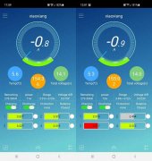
For the four parallel batteries issue, I think it's fine to do that. Periodically, check the charge of each battery to make sure they are all staying about the same. My two 4s batteries are doing well in parallel. Below are screen shots of the two BMS. They look a bit out of sync but I think it's closer than the screen shots imply. Each battery has its own set of warming pads and thermostat and they could have been at opposite ends of the warming cycle (35° F to 45° F). It was quite cold outside that day and snowing. On a subsequent warmer, sunny day, the two batteries looked like identical twins from the app.

BatteryPair.jpg
 
I have multiple Daly BMS Battery Banks connected together without any issue.

You took the Dead one and put it on the working Battery?
Also when doing this the cables from each battery should be the same length and connect to a bus or common point not changed battery to battery.
 
Back
Top