diy solar

diy solar

DALY BMS Issue BMS P- voltage = 8v vs. terminal voltage = 13v

gianni

New Member
Joined
Dec 4, 2020
Messages
3
Hi everyone,

My setup:
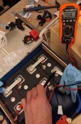
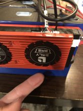
BMS: DALY BMS 4S 12V 120A
Cells: 277ah ETC

My issue:
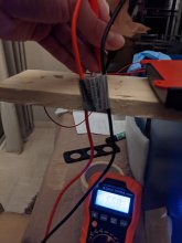
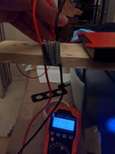
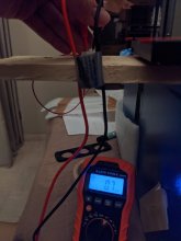
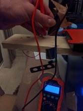
When multimeter connected at P- on BMS and main positive it reads a very low voltage: around 8.36v (see pictures)
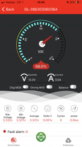
Although when multimeter connected directly on the main positive and main negative it reads 13.36v

Steps taken to troubleshoot:
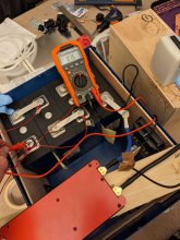
Checking cable leads one by one with negative and moving up, it seems to be working on lead 1, 2, 3 but the last lead doesn't show the expected voltage of 13.36v but 0.7mV (see pictures)

Questions:
1) I did try the P- B- to reset the BMS as suggested here: https://diysolarforum.com/threads/d...s-26-22v-of-the-battery-pack.5040/#post-50930 with the leads connected is that the correct way or am I missing something? I didn't have any spark.
2) as of now I haven't put any load or charger (I charged by top balancing the cells in parallel with power supply) should I try? Is there any incidence?

Sorry if there is an obvious step I haven't taken, this is my first build.

Thanks for your help!
 

Attachments

  • 01PXL_20210108_011635125.jpg
    01PXL_20210108_011635125.jpg
    131.2 KB · Views: 33
  • 03PXL_20210108_011502900.jpg
    03PXL_20210108_011502900.jpg
    83.3 KB · Views: 32
  • 02PXL_20210108_011451780.jpg
    02PXL_20210108_011451780.jpg
    73.9 KB · Views: 32
  • 05PXL_20210108_011438679.jpg
    05PXL_20210108_011438679.jpg
    79 KB · Views: 31
  • 04PXL_20210108_011425508.jpg
    04PXL_20210108_011425508.jpg
    76.3 KB · Views: 30
  • 00PXL_20210108_012637359.jpg
    00PXL_20210108_012637359.jpg
    148.5 KB · Views: 33
Did you put a charging voltage on it with psu?
Shorting the p-and b- didn't work for me either.
That is what I had to do also to wake up my two DALY 4S 100A in my two battery packs, put the charger Voltage to the pack..
And also what ever you do, make sure to disconnect the balance cable plug from BMS before disconnecting all other cables from batteries..
 
Last edited:
That is what I had to do also to wake up my two DALY 4S 100A in my two battery packs.
And also what ever you do, make sure to disconnect the balance cable plug from BMS before disconnecting
Also a discharge works also to wake up
 
Did you put a charging voltage on it with psu?
Shorting the p-and b- didn't work for me either.
No I didn't, I put it once the pack was fully charger but didn't add the PSU once BMS was connected. I will try

That is what I had to do also to wake up my two DALY 4S 100A in my two battery packs, put the charger Voltage to the pack..
And also what ever you do, make sure to disconnect the balance cable plug from BMS before disconnecting all other cables from batteries..
Thanks, I didn't know that. Out of curiosity, why is that?
 
No I didn't, I put it once the pack was fully charger but didn't add the PSU once BMS was connected. I will try


Thanks, I didn't know that. Out of curiosity, why is that?
Don't connect bms when fully charged it may see that as hvd...do everything at 50%soc
 
Same issue with my 400a smart bms. wont turn on. cant charge it. can discharge it. everything checked. shorting the leads does nothing. shows close to pack voltage on the p- lead but if i disconnect the b- lead from battery and the neg balance lead the p- still shows voltage so its just the voltage coming from the balance leads nothing is actually passing through the bms from the battery main connection.
 
IIRC, but a document which I saw from Daly (I think it was from the "Resources" on this site), warns not to short out B- to P- (saying that they will not accept a return on a unit where this was done). Their instructions specified that you need to set a DVM to measure resistance (in ohms). But many people here HAVE had success with shorting those leads, I'm not sure what to do.

In making a connection through the DVM, it splits a tiny test current through a comparator, while testing for resistance. Maybe this process avoids "killing" components within the BMS.

In going slightly OT - I'm unsure about the order of making Daly BMS connections. Does the plug with the individual cells go in LAST (with wires already connected), or do the cell wires get connected individually (starting with "-") while the plug is in place? And should that be done before balancing and connecting "P -", or should "P -" be the second last thing? I assume main "12V" connection to the system bus to be the last thing.

Please advise.
 
Last edited:
IIRC, but a document which I saw from Daly (I think it was from the "Resources" on this site), warns not to short out B- to P- (saying that they will not accept a return on a unit where this was done). Their instructions specified that you need to set a DVM to measure resistance (in ohms). But many people here HAVE had success with shorting those leads, I'm not sure what to do.

In making a connection through the DVM, it splits a tiny test current through a comparator, while testing for resistance. Maybe this process avoids "killing" components within the BMS.

In going slightly OT - I'm unsure about the order of making Daly BMS connections. Does the plug with the individual cells go in LAST (with wires already connected), or do the cell wires get connected individually (starting with "-") while the plug is in place? And should that be done before balancing and connecting "P -", or should "P -" be the second last thing? I assume main "12V" connection to the system bus to be the last thing.

Please advise.
OK FIXED MINE! SO>>>>> wire the bms wires all of them to the battery. then if they are in correct order plug them into the bms as well as the temp probe and uart or bluetooth. THEN YOU MUST use the omh tester between the b- and p- wires test if showing only small number. THEN ONLY THEN attach the b- blue wire to battery WHILE KEEPING THE BALANCE NEG STILL ATTACHED. THEN check total voltage with meter on the battery positive and p- wires. if it shows correct pack voltage it will work. AND mine finally did. believe it or not you have to do it in that order. i am also told NEVER DISCONNECT BALANCE LEAD WHILE B- IS STILL CONNECTED.
 
OK FIXED MINE! SO>>>>> wire the bms wires all of them to the battery. then if they are in correct order plug them into the bms as well as the temp probe and uart or bluetooth. THEN YOU MUST use the omh tester between the b- and p- wires test if showing only small number. THEN ONLY THEN attach the b- blue wire to battery WHILE KEEPING THE BALANCE NEG STILL ATTACHED. THEN check total voltage with meter on the battery positive and p- wires. if it shows correct pack voltage it will work. AND mine finally did. believe it or not you have to do it in that order. i am also told NEVER DISCONNECT BALANCE LEAD WHILE B- IS STILL CONNECTED.
timmeh, Thank you!

This was perfect, Daly should hire YOU to write their English instructions :p
 
timmeh, Thank you!

This was perfect, Daly should hire YOU to write their English instructions :p
I searched high and low for an answer but found none. and once I figured it out i made sure i posted it here as I’m sure others had the same issue. The instructions that it came with were so poorly written i could not understand them to picture the steps in order and why they needed to be done. Do not short the p- and b- leads. Daly will not accept a return if you damage the bms. Doing the process above with a multi meter testing the resistance is the key activation method.
 
I have turned your information into a 'resources' post for Daly Smart BMS, here: https://diysolarforum.com/resources...re-to-attach-daly-smart-bms-to-batteries.180/

If anything should be modified, we can work together to replace that post with a new version.
I have turned your information into a 'resources' post for Daly Smart BMS, here: https://diysolarforum.com/resources...re-to-attach-daly-smart-bms-to-batteries.180/

If anything should be modified, we can work together to replace that post with a new version.
Step 7 you check voltage on positce and p- matches pack voltage not resistance test. Resistance check is only done after you attach balance plug. Thanks for adding it to resorces hopefully it helps others. Seems like a lot have had the same issue and it was not faulty bms but incorrect procedure. Hopefully Will sees this and stops shorting leads in his videos as thats why i did it to mine at first as have others.
 
Step 7 you check voltage on positce and p- matches pack voltage not resistance test. Resistance check is only done after you attach balance plug. Thanks for adding it to resorces hopefully it helps others. Seems like a lot have had the same issue and it was not faulty bms but incorrect procedure. Hopefully Will sees this and stops shorting leads in his videos as thats why i did it to mine at first as have others.
If Voltage does not match, wouldn't the correction be to re-run the "resistance check"? (We still don't want to "short" "P-" back to the battery pack "-", where "B-" is now connected.)
 
Step 7 you check voltage on positce and p- matches pack voltage not resistance test. Resistance check is only done after you attach balance plug. Thanks for adding it to resorces hopefully it helps others. Seems like a lot have had the same issue and it was not faulty bms but incorrect procedure. Hopefully Will sees this and stops shorting leads in his videos as thats why i did it to mine at first as have others.
Yesterday my BMS connected and powered on by shorting.
Today my BMS shut down due to over-current fault, and now upon reconnecting BT, my BMS is not working to power any loads. It is giving me accurate cell voltages and when I connect to 15v charger it powrrs on and allows BT connection like normal.
But it doesn’t do anything else. As soon as I disconnect my bench supply, my 12v load is unpowered. BT connection remains but I can’t get the BMS to allow current thru it.
sound familiar to anyone?
 

Attachments

  • E1089B49-39E8-4BDB-85AC-EEE4CB369F8D.png
    E1089B49-39E8-4BDB-85AC-EEE4CB369F8D.png
    671.8 KB · Views: 6
Last edited:
Yesterday my BMS connected and powered on by shorting.
Today my BMS shut down due to over-current fault, and now upon reconnecting BT, my BMS is not working to power any loads. It is giving me accurate cell voltages and when I connect to 15v charger it powrrs on and allows BT connection like normal.
But it doesn’t do anything else. As soon as I disconnect my bench supply, my 12v load is unpowered. BT connection remains but I can’t get the BMS to allow current thru it.
sound familiar to anyone?
Looks like the mosfets for charge and discharge are turned off in settings.
 
If Voltage does not match, wouldn't the correction be to re-run the "resistance check"? (We still don't want to "short" "P-" back to the battery pack "-", where "B-" is now connected. I am not sure exactly but my instructions also say use can use buzzer which i assume means continuity test. Maybe we can add that too. So after attach b- test resistance if looks good test continuity if the buzzer beeps then voltage should also be correct as the bms is now live.
Yes true. So maybe step 7 is connect b- then test resistance. if it looks good you can also test continuity "buzzer" if it buzzes that means we have flow from the battery and bms is live. voltage now if tested should now match the pack. my instructions mention testing resistance or buzzer setting, i'm not sure which one activates the bms but for the sake of process lets stick with resistance followed by continuity to check if its worked followed by voltage as further confirmation.
 
Back
Top