diy solar

diy solar

Daly bms smart 12v 250A

I have a smaller Daly Smart BMS, size 200A. Mine has 3 ports on the opposite side BMS from your first photo (showing the UART port). One of these is labeled "MON". I think that your video is referring to connectors on that back side.
 
Hi everybody,
I'm new here.
I have 4 lifepo4 modules 12v 280A on my boat, with solar panel, dc-dc charger, 220v 2kw charger, daly bms smart 250A

I 'm not be able to attivate my bms

Some video suggest to shortcut pin 6-8, other pin 1-3. But I'have not the port in video

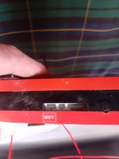
Someone can help me?View attachment 86866View attachment 86867View attachment 86868

Read thru the whole thread, the pins you need are the two where the light board would attach.
 
Not sure if your 250a BMS is configured the same as our 200a Daly Smart BMS. On the same side as the black P- cable, there is 3-pin connector labeled "Monitor", an unlabeled 2-pin connector, and another unlabeled 6-pin connector, all located right next to each other. The 2-pin connector needs to be temporarily shorted to "wake-up" the BMS.
 
I have a smaller Daly Smart BMS, size 200A. Mine has 3 ports on the opposite side BMS from your first photo (showing the UART port). One of these is labeled "MON". I think that your video is referring to connectors on that back side.
Hi, thanks.
In the other side I have this port...
Not sure if your 250a BMS is configured the same as our 200a Daly Smart BMS. On the same side as the black P- cable, there is 3-pin connector labeled "Monitor", an unlabeled 2-pin connector, and another unlabeled 6-pin connector, all located right next to each other. The 2-pin connector needs to be temporarily shorted to "wake-up" the BMS.
Hi,
Thanks everybody.
In the other side, black cable side, I have this in photo.
I hope this is monitor...

20220312_112010.jpg
 
You can also jumper across battery negative post and the (P-) cable, and that will turn the bms on too.
 
You can also jumper across battery negative post and the (P-) cable, and that will turn the bms on too.
I don't recommend doing this, because Daly very loudly proclaims that any attempt at "fusing" B- and P- in this way voids your warranty. (Doing that can apparently destroy the BMS in some circumstances.) Short-circuiting the 2 pins is a better idea.
 
I don't recommend doing this, because Daly very loudly proclaims that any attempt at "fusing" B- and P- in this way voids your warranty. (Doing that can apparently destroy the BMS in some circumstances.) Short-circuiting the 2 pins is a better idea.
Hi everybody.
My bms is dead...
This morning was 0 Volts, battery pack was ok, 12,8....
I short-circuit 2 pins, but not reset.
What can I do?
Thanks
 
Hi everybody.
My bms is dead...
This morning was 0 Volts, battery pack was ok, 12,8....
I short-circuit 2 pins, but not reset.
What can I do?
Thanks
Can you attach a charger? With the pack reading only 12.8, the BMS should happily "wake up" and accept charge current, as long as the charger is supply more than 13.6V. (I have a small "6A, 14.6V" charger which can do that.)
 
Hi everybody.
My bms is dead...
This morning was 0 Volts, battery pack was ok, 12,8....
I short-circuit 2 pins, but not reset.
What can I do?
Thanks
Rickst29's suggestion is definitely worth a try.

If no luck: Hopefully this a Smart BMS (with bluetooth/USB access)? Any faults? Is the discharge mosfet open?

Sometimes erroneous values in the ChargeBackupDelay and PowerDownDelay fields (in Sinowealth) will cause the Daly to go into a sleep mode where even the 2-pin connector won't work. It's been a long time since I dealt with this similar issue (we've since replaced our Daly with a JBD). I believe the correct entry for both fields was 255. Even after verifying these fields I'd also suggest disconnecting everything (including the balance leads) and powering up the BMS from scratch again.

Good luck!
 
Last edited:
Rickst29's suggestion is definitely worth a try.

If no luck: Hopefully this a Smart BMS (with bluetooth/USB access)? Any faults? Is the discharge mosfet open?

Sometimes erroneous values in the ChargeBackupDelay and PowerDownDelay fields (in Sinowealth) will cause the Daly to go into a sleep mode where even the 2-pin connector won't work. It's been a long time since I dealt with this similar issue (we've since replaced our Daly with a JBD). I believe the correct entry for both fields was 255. Even after verifying these fields I'd also suggest disconnecting everything (including the balance leads) and powering up the BMS from scratch again.

Good luck!
Hi,,
I disconnect the bms and reconnect.
It start without short-circuit pins.
Thank you
Alberto
 
Hello everyone.
I have a problem that I would like to submit to the forum.
I live on my boat, not in port, and I have this system:
2 x 100w solar panels
1 mppt regulator
1 monitor
1 dc-dc chargher 30A
1 lifepo4 12V 280Ah
1 daly bms 250 Ah
1 inverter 3kw-6Kw.

220v household appliances:
fridge A +
food processor (400W) 15-20 minutes per day
coffee machine (350 W) 15 minutes a day (4 coffees X 2 times usually)

Water heater (1200W) 20 minutes every other day
electric grill (1200W) 20 minutes sometimes

The first time I mounted the system the bms gave 90% charge, and so I charged with the dc-dc charger until I had 100% (display on the charger gave 0A)
I normally used the fridge and the coffee machine and the solar panels managed to guarantee enough current (after 10 days I had 80% charge)

Then I tried to use the water heater, but the voltage drop (up to 10.6 V) causes the inverter to trip (is this normal? Is the discharge too violent?)

Then I had a few days without sun, and the battery went down.
everything ok up to 53%, and I was quiet, then the bms disconnected everything (at night) and we were left in the dark (luckily I have a generator)
As soon as the generator was turned on, the Daly monitor gave 0%.
After 30 minutes (25Ah x 1/2 hour = 12A) everything started again and the bms monitor gave 3%.
In the morning the Daly monitor gave 40%, without having added power, then I charged 2 hours with the generator (25Ah X2 hours = 50A) and the monitor gave 50%.

Now the sun is back, the panels are charging, the Daly monitor gives 60%, but during the night everything is still turned off, and, after turning on the generator, the Daly monitor was giving 1%.

How is it possible that the Daly monitor is unable to measure the real state of charge of the batteries?
The Victron Monitor also gives charged batteries, but unfortunately, below 53% the bms drops and leaves us in the dark.

Does anyone already have similar experiences?
There is a solution ? or just don't go below 53%?

thank you very much for the time you dedicate
Alberto
Your Daly "smart" BMS is unable to report the genuine State-of-Charge (SOC) of a controlled battery. Information displayed on the Victron is generally better. (I have smaller Daly BMS "Smart" BMS than you do, only 200A, and a smaller battery pack - but that battery pack can easily handle continuous loads in excess of 1200 Watts through a 120-VAC inverter.)

The water heater is a purely resistive load, but runs at full power for a long time. Your 1200W heater unit would require about 1500W input from the battery to the Inverter, if efficiency is about 80%. At roughly 12.8V in well-configured discharge, this is about 120 Amps.

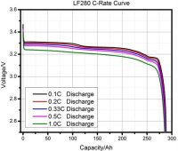
You may note, from the attached graph, that the LFP cells (if EVE, and rated for 1C) have very little voltage drop within the cells themselves (while supporting this current, and with more than 50% SOC remaining). The problem is almost certainly in your wiring:

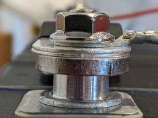
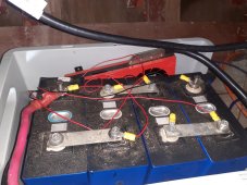
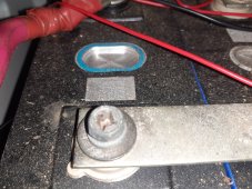
Your 3 Bus Bars, between battery cells, need to be very large. Bus bars which are sent "for free" with battery cells are never big enough to handle your needs. You need to either stack multiple little ones (perhaps 4 of them on each bus) or obtain a much bigger one. The second photo shows
my own bus bar assembly, used for my EVE-230Ah cells, with a double pair pressed in to possibly assist the very large "main" bar underneath. The bolts must also be properly tightened, using a small torque wrench.

Between the battery pack and the "12V" Inverter connector lugs, you also need some big cables. Pairs of AWG 2/0 on each terminal, or a single AWG 4/0, should be adequate if lengths are not excessive. I don't know the equivalent EU cable sizes, but you can look them up pretty easily.

When the household fridge starts the compressor, there is short term but very high current draw for "compressor start". This is possibly 7x greater than the rated power of the fridge, and may be associated with the specific shutdown events.
- - -
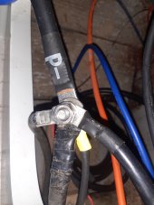
In short, I am inclined to blame bus bars or inverter's "12v" supply wires, as the likely cause of low voltage problems. Can you post a photo for one of your 3 bus bar assemblies, and are you sure that the bus bar terminal nuts have been correctly tightened?
 

Attachments

  • Eve-LF280Ah-discharge-curve.jpg
    Eve-LF280Ah-discharge-curve.jpg
    32.2 KB · Views: 4
  • Eve-triple-terminal-bus-bars..jpg
    Eve-triple-terminal-bus-bars..jpg
    315.6 KB · Views: 4
Thanks a lot for the answer.
As a bus bar I used the ones provided, but now I will redo them in copper, with a double 12mm pipe. (2 copper bus bars + the one supplied)
I used the supplied cables to connect the inverter, but I can double it, it's not a problem.
But now I have another doubt:
the cables from the solar panels arrive directly (there is a safety magnetothermic) to the P- of the bms and to the P + of the battery pack.
Do you think it could interfere with the reading of the victron? because it is not accurate ...
What do you think if you put the connection downstream of the victron shunt? So the value of the panels would not be measured.
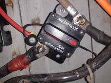
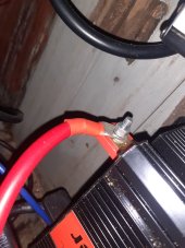
Attached I have inserted:
battery pack with existing connections
bus bar
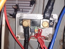
wiring P-
inverter output cable +
battery circuit breaker
victron shunt

thank you very much for your time and the advice you want to give.
Alberto
 

Attachments

  • - pole.jpg
    - pole.jpg
    126.8 KB · Views: 6
  • battery fuse.jpg
    battery fuse.jpg
    318.7 KB · Views: 7
  • battery pack.jpg
    battery pack.jpg
    282.6 KB · Views: 8
  • bus bar.jpg
    bus bar.jpg
    389.5 KB · Views: 7
  • inverter cable.jpg
    inverter cable.jpg
    135.7 KB · Views: 7
  • victron shunt.jpg
    victron shunt.jpg
    275.3 KB · Views: 6
Your photos were helpful, thanks. The bigger bus bars should be plated copper, not left "naked".

I would prefer to have the Victron measuring all of the "P-" current into the batteries, inclusive of solar. This will effectively make the Victron a monitor of the battery pack only, rather than attempting to monitor only a subset of "P-" loading and charge sources.

P- connects only to Victron. Victron, on the non-battery side, connects a bus of all grounding current leads, both charging and discharging. (Charging leads "Bat -" lead from the MPPT Solar.

It is unclear whether Generator provides 220-VAC to a "shore power" CONVERTER, or DC into the DC->DC converter. If the DC->DC converter is used from an SUV/Truck battery or other DC supply (not the generator), then Generator/Shore is a separate power source (through a converter, which may or may not be programmed "to charge LFP" versus AGM versus SLA.)

But in any case, I recommend that the Victron be exclusive to the battery loading. Charging Sources (220-VAC Converter or DC->DC) which are directly consumed by the Inverter or other loads will not be seen by the Victron in my wiring modification plan.

Both Solar cables should be fused separately between panels and MPPT, with class-T fuses (high voltage and fast-blow). Although "Solar -" may be fused to "Bat -" within the MPPT, it should be protected from a lightning hit before it reaches MPPT, with MPPT non-conductive failures and Victron shunt non-conductive failures being unlikely protections from the case of a lightning strike.

From the big "-" bus bar (in your case, a screw) one large cable leads into Victron. The other side of Victron may directly connect "P-". If the Victron shunt bolt is incompatible with the BMS lug hole you may either (1) cut off the current Daly Lug and replace it; or (2) use a reduced bolt within the shunt; or (3) use a short jumper with compatible lugs in between. #3 adds more wire length and resistance, I recommend against that. #2 may require an undesirable washer, so I generally recommend against that as well.

In my own case, with the Daly P-" jumper consisting of only AWG 2/0 wire for several inches, I cut the Daly jumper short and mounted a new lug. Voids the Daly guarantee, of course.
 
Hi,
thank you very much for helping.
As soon as I have made the changes I will post them.
The 220V ac generator powers a quick sbc marine battery charger which charges the 12v (lead acid) battery of the boat engine, similarly to the engine alternator when it is switched on.
Above 13V the adjustable 30A dc-dc charger is activated and recharges the lifepo4 battery pack (obviously I put a protection and release circuit breaker)
The plants are separate (no - in common).
In this way I can charge both with the generator and with the engine of the boat.

we have documented the restoration of our boat, even if it is not updated yet.
if you are curious: larottadiberenice.com

thank you
Alberto
 
Back
Top