loopyengineering_co
New Member
- Joined
- Mar 18, 2022
- Messages
- 4
Hi guys.
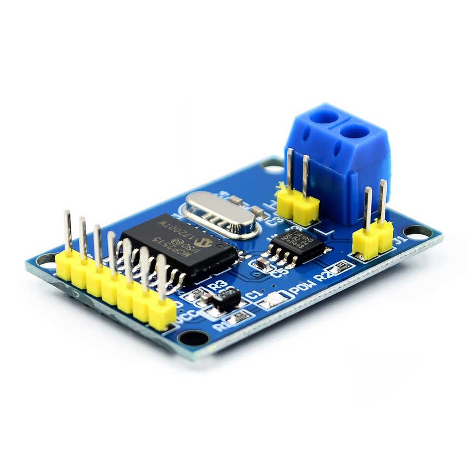
I've made a thingie that allows you to use the Daly BMS with Sofar inverters (and others that use the SMA canbus protocol).

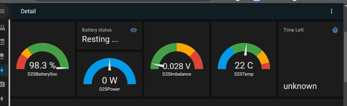
It talks to Daly via UART (where the Bluetooth dongle plugs in), translates the data and sends it via CANBUS to the inverter to keep it happy, and also connects to WiFi, subscribes to your MQTT broker and publishes all the data.
I know a lot of people use the Seplos BMS as it has native support for this, but the Dalys have their own advantages and this device also passes very fresh and very frequent data via WiFi (MQTT) to Home Assistant and suchlike.
It's still beta, but it works.
Check it out and give me any feedback for improvement")

 github.com
I've made a thingie that allows you to use the Daly BMS with Sofar inverters (and others that use the SMA canbus protocol).
It talks to Daly via UART (where the Bluetooth dongle plugs in), translates the data and sends it via CANBUS to the inverter to keep it happy, and also connects to WiFi, subscribes to your MQTT broker and publishes all the data.
I know a lot of people use the Seplos BMS as it has native support for this, but the Dalys have their own advantages and this device also passes very fresh and very frequent data via WiFi (MQTT) to Home Assistant and suchlike.
It's still beta, but it works.
Check it out and give me any feedback for improvement
GitHub - loopyengineeringco/Daly2Sofar: ESP32 bridge allowing Daly Smart BMS to be used with a Sofar inverter/charger (and others that use SMA CANBUS protocol).
ESP32 bridge allowing Daly Smart BMS to be used with a Sofar inverter/charger (and others that use SMA CANBUS protocol). - loopyengineeringco/Daly2Sofar
github.com