• Have you tried out dark mode?! Scroll to the bottom of any page to find a sun or moon icon to turn dark mode on or off!

diy solar

diy solar

Darfon Gro Watt GBLI 5001 Battery Pack- worth a punt?

-C-

New Member
Joined
Oct 17, 2020
Messages
15
I've been offered this - seller is fair and flexible, price is somewhat dependent on how useful it'll be for me.
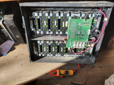
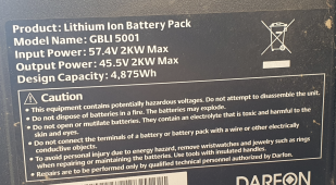
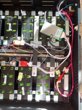
1623952167585.png

1623952322779.png
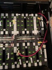
I can't get any sign of life out of the BMS, but that's likely due to the string voltages. Took out one row and this is what they measured at:
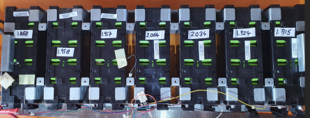
1623952348101.png

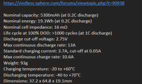
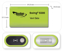
It's using these Boston Power Swing 5300 cells, which from what I've read are pretty good when new.
1623952441761.png
1623952452618.png

As the cells have been discharged well below the specced 2.75V. Is there any hope for them?

If they're likely to be usable or revivable, I'm thinking of reconfiguring it as 24V (my main inverter is 24V) and using a different BMS, as from what I've read the main weakness of these systems is the standard BMS. If that sounds sensible, does anyone have any recommendations for a suitable BMS?

Or should I just walk away?

Thanks
 
If it is REAL CHEAP I'd consider it.
How long have they been below cutoff ? The longer it has been the loss of capacity will increase.
Can they be salvaged ? Possibly, only one way to know, is a nice gentle charge to 3.0Vpc and then observe & measure over a few days to see how much settling occurs from 3.000V per cell.
 
Thanks- I meant to say that he's not sure how long they've been sat for. I'll see if he can find out- he does seem to know the original owner. Info so far has been vague, other than it was installed in an attic and upgraded a while ago.

I'd like to give charging them a try. My issue is with how best to do that. I have these at my disposal:
  1. I have a bench power supply, it's only capable of 3A, up to 60V. Is it worth giving it a try with that? I realise it'll take a while. I'm guessing it'd be best to charge each string individually if using this, rather than sharing those As across multiple strings?
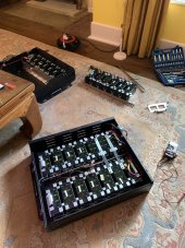
  2. I have the APC UPS that you can see in the top photo. I believe it's working, but the set of VRLAs was dead when I got it. That runs @ 48V- I'm imagining that the voltage of this pack will be too low for it to even start charging...
  3. Some regular Li 18650 chargers that can do up to 1A per cell- could I use those somehow?
  4. A 3.5 kW 24 V Studer inverter/charger that I could connect to the mains. This is highly configurable as far as charging current/ voltage etc.
  5. A few different regular 12 V car LA battery chargers
Or none of those any good?

Could well be real cheap, price will depend on the results of the testing, if I can get them charged : )
 
1st things 1st... All Lithium batteries are FINICKY and each chemistry has a different voltage curve, limits etc... car chargers or chargers for ANY other chemistry is a risk at best to foolishly dangerous. Even Will Prowse had misadventures (costly ones too) with the wrong charger.

Stored in an Attic ? WTF !!! LAST PLACE IN THE UNIVERSE to put batteries, especially ones that are Temp Sensitive ! Especially Hot Temps. And they wonder why the pack died. IF it was me and that was told to me, I'd continue walking as those lived in a highly abusive environment. Believe me when I say, that ALL Lithium loves the same temps as the human being does while wearing a T-shirt & pants, not too hot and not too cold. I'd give him $50 just because of the parts & bits and the possibility that some cells may be OK and only if I was feeling generous. Sorry, not what you hoped to hear I bet, but it's my feeling & opinion.

Now, I CANNOT identify those cells, I do not believe they are LFP (LiFePO4), you MUST know what the chemistry (no guesses) is before attempting to charge them. There is 14 packs of cylindrical cells from what I see, they "could" still be LFP but the specs you posted are not clear on this, there is some odd values if LFP.

Because it is Cylindrical Cells set into "packs", the cells are most likely welded to their busbars internally, the packs likely "may" be separated from each others but depending on how they are interconnected will determine how best to do so.

The BMS is likely in Protect Mode due to undervolt and so won't initialize. (normal behaviour for safety) Often there is a reset to allow it to operate IF charge voltage is present. Every BMS is different, so we would need to know the make, model & version of it and MAYBE info can be found.

The Bench supply if set to 56V/3A may be slow & very gentle but likely the best way to see if they'll come back up IF the BMS can be reset. With that there would be no risk of overcharge at a high rate. FYI NCA, NMC "Li-Ion" chemistries form dendrites in Lo Charge State which can lead to internal shorts & worse.
 
It has been stored for an unknown amount of time at low SOC in a hot environment? Walk away.
 
Thanks all- I've got the ability to play about and test them without making any commitment, so I might as well try.
These were in the south of England- there aren't much in the way of temperature extremes here, so maybe the cells won't have been affected by the temps. But the low SoC for a currently unknown length of time (i'm going to try to get more info on the history) is more of a concern to me. The fact that these have an unusually wide operational temp range (-20 to +60 °C) gives me some hope for them not having been too affected by temperature in their installation location, which is unlikely to have been outside -5 to +35 °C.
Datasheet

The cells certainly seem to be good spec. I thought I'd linked to this previously, but see that didn't work... This is the link to a pretty lengthy discussion about them, with mostly favourable reviews: https://endless-sphere.com/forums/viewtopic.php?t=90938
They aren't cylindrical. Rather than 2 cells together, they're actually 1 cell that's oval wound. There's a video here of a guy cutting one open (I've started it where he's cut it open):
 
Last edited:
A rather belated update on this back-burner project...

I bypassed the BMS and charged the battery very slowly (3 A across all cells until system voltage reached the specified 57.4). This took a long time as I have not been able to get to my workshop much and I did not want to leave it charging while I wasn't there keeping an eye on it.

All cells came up in voltage very evenly, other than strings 7 & 8, which started at lower V so by the time the battery was at the 57.4 V, these 2 were considerably lower than the others. I found that these strings are not monitored by the BMS. There aren't even monitor wires going to these cells. I've never seen this before, seems very odd to me.

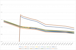
I was impressed with how balanced all of the strings other 7-8 remained during and after charging. All within a few hundredths of a Volt.

Once I'd realised the situation with 7 & 8 & how far behind these strings were, I charged them separately to bring them up to the same voltage as the rest- I inadvertently let them get to a slightly higher V than the other strings, but the maximum they reached was 4.098 V.

I then took a measurement of each string each time I was back at my workshop. The results are below. (The 2 high strings are 7 & 8, which were charged separately).

Initially there was no sign of life from the BMS. I tried again once it was up to voltage. The LED flashed green for a second, then went red. There was no output. I tried long-pressing, double-pressing... There are no marks on the PCB, it appears to be made by Darfon. My guess is that the BMS died, which is why the battery was decommissioned. I have read elsewhere that the BMS in these was not reliable and tetchy old tech.

So my question is, based on these results, the batteries being specified for use in a wide temperature range, the fact it looks like the BMS went bad, the cells seem to be OK considering their age, and that I'd likely be able to buy this for a very good price (that conversation with the owner still yet to be had- he's awaiting me making him an offer), do you think it would be worth buying a new BMS and giving it a go? I guess the only sure way of knowing if they're any good is to try them with a load over a period of time and run them through a few charge/ discharge cycles.

If so, what about converting it to 24 V? Reason being that I have a 24 V, 3.5 kW inverter that I could use this with. The only 48V kit I have is an old APC PSU. It has copper plate interlinks and 10 mm cable between the cells. Would I need to upgrade this? Otherwise, it would mean finding a used 48 V inverter charger and charge controller for a decent price.

Unless these results are ringing alarm bells for anyone, I'm tempted to spend a bit of money to see if I can make use of this. The cost to buy it is likely to be very reasonable, but what would you offer for it considering these results?

Many thanks

Picture1.png

The system voltage

12/07/21​
03/08/21​
04/08/21​
07/08/21​
26/08/21​
02/09/21​
09/09/21​
57.27​
57.13​
57.12​
57.1​
57​
56.96​
56.92​
 
I was actually given one of these Growatt (Darfon) GBLI 5001 batteries for a similar reason. It seemed that one of the cell packs had gone below a recoverable voltage for the BMS to handle so wouldnt charge or discharge. I charged up the one cell pack but have still had no luck getting it to work. I press the wake button and the light comes on green, then goes red.

I even bought a Growatt SP2000 to connect to it in hopes that this might give me some more info about the battery state which it did...but now i cant find any info on what "BMS Error 024" actually means :(

I am now exploring the options of using a third party BMS in order to make use of these batteries which still appear to be good, but then i most likely wont be able to use it with the rest of my existing Growatt system.

Im at a bit of a loss...

If you are offered this battery at a decent price (they seem to sell on ebay for around £400 for a known faulty one and around £700 for a working one) and could make use of the cells regardless of the BMS i say go for it!

Best of luck!
 
  • Like
Reactions: -C-
Thanks- I think I should be able to get this for maybe £100 or less, so definitely seems worth a shot based on those prices.

I think I'm initially going to try it on a small 48V load without a BMS while monitoring the string voltages manually. At least that will give me some idea as to its condition without having to spend any money. If that goes OK I'll decide whether to keep it as 48 V or convert to 24 V and buy a suitable BMS for whichever way I go.
 
Hi

What was the solution did you get a new BMS working, Ive got 5 of these GBLI 5001 that i want to make one big pack with.
 
I was actually given one of these Growatt (Darfon) GBLI 5001 batteries for a similar reason. It seemed that one of the cell packs had gone below a recoverable voltage for the BMS to handle so wouldnt charge or discharge. I charged up the one cell pack but have still had no luck getting it to work. I press the wake button and the light comes on green, then goes red.

I even bought a Growatt SP2000 to connect to it in hopes that this might give me some more info about the battery state which it did...but now i cant find any info on what "BMS Error 024" actually means :(

I am now exploring the options of using a third party BMS in order to make use of these batteries which still appear to be good, but then i most likely wont be able to use it with the rest of my existing Growatt system.

Im at a bit of a loss...

If you are offered this battery at a decent price (they seem to sell on ebay for around £400 for a known faulty one and around £700 for a working one) and could make use of the cells regardless of the BMS i say go for it!

Best of luck!
Hi, I have the same battery with the same error code, did you have any success with it?
 
Hi all,

Unfortunately, i have basically given up on these as i spoke to Growatt and they confirmed that their BMS' lock themselves if they ever hit a situation they cant recover from.

I.E. both of the GBLI 5001 battery packs i have are permenantly unrecoverable because one of the cell packs dipped below a threshold that has caused the BMS to go into a safety mode they cannot be taken out of unless you are a Growatt engineer or i guess have the skills be able to manage the firmware running on the boards.

So, that has just left me with the 28 cell packs which im sure with a decent third party BMS would work well! But realistically not useful for my intended purpose of a grid tied battery that i can utilise with my solar to charge with the sun and discharge at night.

The only option would be an "off grid" solution that i ran a seperate circuit from to power some loads. Perhaps i will give it another look into later down the line, but for now they are just paperweights!

Kind Regards,
Josh
 
Hi, sorry to hear that, at least you are getting answers from Growatt, which is more than I get. There is a GBLI 5001 BMS for sale on ebay atm, but he wants what I think is an unreasonable price of £300. So I have one working 5001 and one 2.5kwh working, but the other is a paperweight for me, but I am tempted to open it and try another BMS.
I have also been watching the vehicle to grid (V2G) here in the UK, which uses the car battery as a storage device, and is obviously 2 way, with OVO and a few others having trialed it, and it appears to be coming soon, so if you have an EV, that will be the most cost effective way of storage and use, as it makes sure the vehicle is topped up for when you need it, can supply grid electric to charge at the cheap nighttime rates, and works with solar.
 
Hi all,

Unfortunately, i have basically given up on these as i spoke to Growatt and they confirmed that their BMS' lock themselves if they ever hit a situation they cant recover from.

I.E. both of the GBLI 5001 battery packs i have are permenantly unrecoverable because one of the cell packs dipped below a threshold that has caused the BMS to go into a safety mode they cannot be taken out of unless you are a Growatt engineer or i guess have the skills be able to manage the firmware running on the boards.

So, that has just left me with the 28 cell packs which im sure with a decent third party BMS would work well! But realistically not useful for my intended purpose of a grid tied battery that i can utilise with my solar to charge with the sun and discharge at night.

The only option would be an "off grid" solution that i ran a seperate circuit from to power some loads. Perhaps i will give it another look into later down the line, but for now they are just paperweights!

Kind Regards,
Josh
Are you looking to sell the battery?
 
I have fixed one of these with a BMS fault error'ed battery. I removed the existing BMS and fitted a third party unit. Hooked up monitor wires and set Growatt as lead, and it works perfectly!
 
I have fixed one of these with a BMS fault error'ed battery. I removed the existing BMS and fitted a third party unit. Hooked up monitor wires and set Growatt as lead, and it works perfectly!
What BMS did you use?
 

The 14S 50A

Took about 3 weeks to arrive

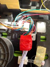
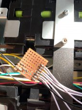
I connected the BMS to the battery sensor wires using 2 veroboards. The red side has 8 wires and the black side has 7. Pretty poo pants when I accidentally touched 2 lines together by accident... I then hot glued the wires and wrapped in loads of insulation

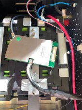
The high current black output goes to the top corner of the board
The high current black from battery to the bottom middle of the board

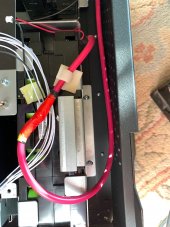
The high current reds are connected together and add loads of thick insulation

The BMS has a temperature sensor, I popped this inbetween 2 cells, just like the original sensors were placed, and hot glued it in

I cable tied the board to the metal strut left by the old BMS

Set Growatt as lead

You'll need an NTC sensor plugged in. I didn't have any, so I used a 10K variable resistor (which didn't need any adjustment), on lines 2 and 8 of the RJ45 socket, and Growatt immediatly started working

I'm using an SP3000 and it charges on solar and off-peak electric. I have 3 other batteries to do

Hoping I can parallel in 2 batteries onto the SP3000's to get more storage, but need to find out how long it takes to charge one first, as I only have 4 hours of off-peak electric

I'm just finishing off my 2nd battery right now
Thanks for that. I have 2 GBLI5001 and a Growatt 2.5kw. One of the 5kw has a bad BMS and in one of the cell packs, it has 7 bad Swing batteries. I plan on ordering replacement batteries and putting a new BMS in, but thinking about making the 3 into one big battery or trying to daisy chain them, still undecided on which way to go.
I have an SP2000 and an SP3000, I think I will sell the SP2000 and try to run the 3000 to 2 batteries, but i am having trouble getting it to output, though it charges the battery just fine. I have to take a look when I have more time to see what I am dong wrong, as it only puts out a few watts on discharge.
 
I had 2 GBLI5001's with bad packs. Batteries leaked. I swapped about so made a good unit out of 2. Looking inside each cell pack the batteries are welded. Which doesn't make replacing the actual batteries easy. I was thinking of just keeping what I have and trying to find a couple more whole units, but prices have gone silly now

I see there's a guy on FB Maketplace selling ex EV batteries - 50kWh for £5000!

Can't comment - yet - on the output of the SP3000. I will have to check. I did notice yesterday evening that I was still importing but had 2 full batteries. My units are set to Force Discharge 04:30 -> 23:59. I was still producing solar at the time. It seems - I may be wrong - that the unit will only go into discharge mode if there's no solar at all.
(Edit - See my later post about the software bug. Force Discharge must be done on the SP3000's menu - the software (Ver 2) doesn't seem to work)

BTW for anyone reading this, NEVER try to upgrade the firmware on the SP2000. It is an extremely easy way to brick them. I managed to do that to 2 units, but luckily Growatt swapped them. I doubt anyone else will be so lucky. You don't gain any funtionality by doing a FW upgrade anyway. All SP2000's can do Force Discharge mode, you just need the software to configure it via a PC
 
Last edited:
I've now paralled up 2 batteries onto 1 SP3000. Seems quite happy

Here's my fake NTC sensor for the SP2/3000. I used White/Orange and Brown, that's Pins 2 and 8 on the SP2/3000

IMG_6304.JPG
 
Are you looking to sell the battery?
Apologies for the delay in response! I have since battled with the SP2000 i have to convert from Li-ion to Lead which was a total pain due to the lack of documentation, but i managed it and since got it set up with an NTC (cant remember the value) spoofed load going through a janky a$$ CT clamp and managed to get it producing power using the battery as the source! So naturally i am spurred on by this success and plan to keep both batteries and convert to a DIY BMS.
 

The 14S 50A

Took about 3 weeks to arrive

I connected the BMS to the battery sensor wires using 2 veroboards. The red side has 8 wires and the black side has 7. Pretty poo pants when I accidentally touched 2 lines together by accident... I then hot glued the wires and wrapped in loads of insulation

The high current black output goes to the top corner of the board
The high current black from battery to the bottom middle of the board

The high current reds are connected together and add loads of thick insulation

The BMS has a temperature sensor, I popped this inbetween 2 cells, just like the original sensors were placed, and hot glued it in

I cable tied the board to the metal strut left by the old BMS

Set Growatt as lead

You'll need an NTC sensor plugged in. I didn't have any, so I used a 10K variable resistor (which didn't need any adjustment), on lines 2 and 8 of the RJ45 socket, and Growatt immediatly started working

I'm using an SP3000 and it charges on solar and off-peak electric. I have 3 other batteries to do

Hoping I can parallel in 2 batteries onto the SP3000's to get more storage, but need to find out how long it takes to charge one first, as I only have 4 hours of off-peak electric

I'm just finishing off my 2nd battery right now
That is brilliant work and great news! I assume the BMS you linked doesn’t have any management of sorts to be able to limit current or change upper and lower charge limits, etc?

On another note, i assume you have a genuine Growatt wired CT clamp with your set up? I didnt get one with mine and have managed to make it “work” with one of my spare CT clamps from my whole home power monitoring solution, but the values appear to be well off those that are reported by the SP2000. If i apply a 1KW load for example, the SP only registers a few hundred Watt. :(


So, naturally i am on the hunt for a Growatt wireless CT clamp as i know this will work for sure and it will allow me to leave the whole installation in my garage where it currently is which unfortunately is on the opposite side of the house to the incoming lines and consumer unit meaning i cant use a wired CT as the length of cable incurs too much loss.
 
I'm so glad I found this thread! Well done to all those persevering with the Growatt SP2000/3000 and GBLI5001's. I bought the SP2000 & GBLI5001 battery a little while ago. All worked ok after setup. I also realised that, by default, the SP2000 doesn't allow the battery to discharge until there is zero power from the PV panels. Annoying as the panels are still producing a handful of watts at nearly 9pm in the summer after which my need for electric is negligible. I was trying to switch on 'Force Discharge' mode, but I could not get the software to run let alone change a setting. I have since broken the SP2000; disconnecting the PV panels without following proper on/off procedure - always follow the on/off procedure! I'm pretty sure the GBLI5001 is ok, however, now it won't charge. I managed to manually charge it to nominal voltage about 51.5v for now while I work out what to do. The SP2000 displays error messages: 'Battery Open', 'BMS Error: 256' and 'PV Short-circuit' too and won't do it's job - so frustrating!

The manual is not very helpful when it comes to remedying faults. It either says 'Check cables' or 'Contact Growatt'. I've done both. Growatt asked me to go through startup procedure carefully. No luck there. Then they pronounced the SP2000 dead.

Thanks for all the ideas: I think the BMS would only listen to Growatt inverters, so changing the Darfon BMS should allow other inverters to use it if they can charge 48v setups. Or connecting the RS485 cable' pins is a good idea - well done to Mike_Hug for discovering. I am looking for another SP2000 (or SP3000) now. Brs98 you mentioned you might have a spare, if you still have one to sell I would be interested! JoshCliffeJones changing SP2000 to assume a lead battery instead might be an option. Incidentally, the CT clamp can work over a fair distance with a good quality network cable. Mine worked ok with almost 17m of network cable and apparently you can get wireless CT clamps to work too. Mind you I always thought that there was a delay in the SP2000 issuing power from the battery. For example if I switched on the kettle (at night) it would take a while for the SP2000 to commit sufficient power from the battery, by which time the kettle has boiled already. Thinking about it now it might be the length of the CT clamp cable creating that delay. Or it might just be slow readings/measurements whilst the electric does actually flow instantly - I'm not convinced though!

Quick query too - when the GBLI5001 is disconnected from everything is there a normal voltage reading at the Anderson plug on the side (either when the status light is on or off)? My GBLI5001 has no reading, but inside directly probing the batteries with a volt meter it does read 51.5v. Is this by design, where the (original Darfon) BMS only allows voltage at the plug when told to do so by the SP2000 via the RS485 comm? I'm thinking about my 'Battery Open' error message and whether it can't 'close' the circuit, it might lead to my BMS being faulty too. If someone could check their battery for voltage at the Anderson plug that would be helpful.

I think the SP2000 is pretty poor as it is not easily configurable and there's no real data monitoring or logs. But I would like to use my GBLI5001 rather than it just sit there. If I can't replace my faulty SP2000 or find a SP3000 then I’ll find an inverter with battery charging features (and good monitoring/logging features too) so I'd love to hear more about your experiences replacing the Darfon BMS with the JBD one and if anyone can recommend a good inverter/charger. Good luck everyone with keeping these batteries operational.
Indeed i am also thankful for the other DIY solar hobbiests found here too! Its always good to find a helpful community! :D

I wondered what the behaviour was for discharging the battery...wasnt sure if it only aided in supplimenting incoming solar to match the load or whether it only worked once there was no longer any solar. I too saw the "forced discharge" option which i have set to on...but again little information about how this "forces" it.

It sounds like you certainly need a new SP2000/3000, thankfully these seem to come up fairly regularly on ebay and the like as its normally the item that outlives the GBLI5001!

I have just purchased 2 x Daly Smart BMS' with bluetooth and UART capabilities which i will be installing into the two GBLI5001 packs i have, as they are "smart" they will at least allow me to more easily monitor the batteries condition and most importantly set the desired upper and lower voltages in order to maintain safety. I have also changed the SP2000 over to "lead acid" already so i can simply supply it with a battery.

The issue i had with the CT reporting false numbers as i found out was due to the CT i was using. I have since bought a new CT with a rating of 100A:100mA which appears to read far closer to the real consumption, seems to be around 150W off still, but im happy with it until i can find a genuine Growatt CT :)

I will post a new dedicated thread once i have everything in place and in working order to share with the community and assist/inspire anyone who is interested in such a thing!

With how energy prices are going, its a good time to get into the DIY solar game!
 

diy solar

diy solar
Back
Top