diy solar

diy solar

DC Circuit Breaker Fires!!

I recently installed a new MPPT solar controller in my RV. While I was researching new SCC I stumbled upon a couple web sites talking about the proper way to switch solar panels on and off using a DC circuit breaker. So I ordered this one from AMAZON:

https://www.amazon.com/gp/product/B096315TSJ/ref=ppx_yo_dt_b_asin_title_o07_s01?ie=UTF8&th=1

DC Miniature Circuit Breaker, 2 Pole 1000V 63 Amp Isolator for Solar PV System, Thermal Magnetic Trip, DIN Rail Mount, Chtaixi DC Disconnect Switch C63"​

I'm seeing where some DC circuit breakers have the leads switched on bottom and top....+ on the left on top and + on the right on bottom, and opposite for -.

This circuit breaker only calls out +/- on one end......There are no markings on the other end.

If you look at the attached link, there is some type of schematic on the front calling out 1,2,3,4....I'm not sure what this means.

I have it connected + to + and - to - running straight through the breaker..... Is this correct or am I going to burn my RV to the ground?

Three 140w / 12V panels in parallel.....with 4g wire of 25' to SCC
So to fix this....Connect source and loads negatives together if you can, so you don't have that dc voltage potential across those shitty China substandard breaker. Just switch positives. And throw those China breakers away. They suck.
 
Probably why they failed catastrophically at those potential. The flipping of the terminals means that the traces are crossed internally and if the two traces are close enough to one another at the crossing, poof!
Breaker has no idea which direction current flows. Just trips when it's bimetal element sees sufficient heating, tripping the switch. Substandard China shit breakers though seem to know how to defy their ratings and fail miserably.
 
I have a few of those same Amazon circuit breakers. A 100A overheats and trips at 85A. It went in the trash. A second one is cool at 85A.
45a? I put in 4 150a breakers and they tripped below 30a. Lucky i didnt have a fire. I do forensics engineering, I am working a case in Maryland, a $20 rapid shutdown device serving 2 rooftop modules on a half million wtt system caught fire and burned half the million square foot roof off. Huge claim, with major subrogation lawsuits in different directions. I represent the building owner. 4 tenants insurance companies just now getting involved. The email list is like 4 lines long, probable 8 or more of us EEs on site next inspection. Really glad I am not Engineer of record on this one. Nothing to do with the failure, but the lawyers will sit after next inspection, after our lab analysis determines fault, and place proportional blame on all parties and proportion the liability payments. Big racket.
 
Last edited by a moderator:
And throw those China breakers away. They suck
There's nothing wrong with this particular breaker.
If, wired correctly.
I have personally verified that it can extinguish a 450vdc arc.
Breaker has no idea which direction current flows. Just trips when it's bimetal element sees sufficient heating, tripping the switch.
Polarized dc breakers require directional circuitry.
 
There definitely are cheap Chinese breakers on the market. But, that's not one of them.
 
I am revising my van setup. Without restarting the pizzing contest above, I could sure use some advice regarding a breaker / disconnect switch between the solar panel and the controller (“input” to the controller) BECAUSE I will be frequently switching the “output” from the controller between 2 different battery banks. I will soon have a higher voltage panel (250w, 51Voc, ~6a) and leaning toward a Victron Smart 100/20 solar charge Controller. I am not an EE (obviously), but am trying to use some common sense. I understand one part of the pizzing contest, and I side with higher-voltage-capable breaker. I want the convenience of a “switch” or breaker. ***My real question whether I need BOTH + & - wires interrupted by the breaker?*** Explorist Nate says yes (for code reasons???), whereas Will P seems OK with positive lead only…from what I have seen.

For convenience sake, I’ve toyed with using a 3PDT switch (or maybe it would need to be a 4PDT) so that it’s impossible to switch battery banks without interrupting the solar at the same time. In other words, 1 toggle would control both the “input” side as well as the “output” side of the controller. Such a “high” capacity switch is hard to come by in the 3P or 4P versions (26 week lead time). Today I have separate switches (1 for “in”, 1 for “out”), and often enough flip only the “output” switch, without worrying about the “input.” Morningstar support (for my current PWM controller) doesn’t condone this behavior, but nothing has smoked yet. They actually said the danger is to the downstream (“out”) loads getting fried, not the controller itself. I started worrying because the new panel is over twice (more like 2.5x) the voltage of the panel I spoke to Morningstar about, and there will be more amperage downstream of the controller than I have now, and I know nothing about the robustness of the proposed Victron.
Just a caution.
Before you disconnect the battery from your charge controller, you need to disconnect the solar panels. Some, if not many, charge controllers will be damaged if the panels are connected without a battery connected. Good luck with your system.
 
Breaker has no idea which direction current flows. Just trips when it's bimetal element sees sufficient heating, tripping the switch. Substandard China shit breakers though seem to know how to defy their ratings and fail miserably.
It's not about current flow with regard to direction. It is about arc extinguishing......
 
Before you disconnect the battery from your charge controller, you need to disconnect the solar panels.
Actually this isn't really true but it's a safe habit.

SCCs are not damaged if they lose battery power while still connected to PV.

Some, if not many, charge controllers will be damaged if the panels are connected without a battery connected
Most (if not nearly all) SCCs must be connected to a battery first the first time it is ever connected to anything. This is so the SCC can properly detect the system voltage. Some SCCs will remember that setting even if power is disconnected.

The most important thing is to connect battery power first then connect PV. It's probably a good habit to disconnect PV then disconnect battery power if needed. But if the battery is disconnected first and then PV, nothing bad will happen. Just make sure the PV is disconnected before reconnecting battery power. Though technically some SCCs won't care beyond the initial power up.

When in doubt, always try to ensure the PV is disconnected anytime the battery power is connected or disconnected.
 
Breaker has no idea which direction current flows. Just trips when it's bimetal element sees sufficient heating, tripping the switch. Substandard China shit breakers though seem to know how to defy their ratings and fail miserably.
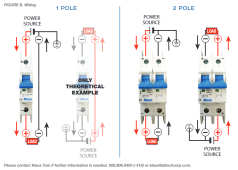
Wiring of a polarized breaker has come up often, so this may be useful to someone " ... Polarized DC circuit breakers use a small magnet to direct the arc away from the contacts and up into the arc de-ionization chamber. If the direction of current flow through the unit is reversed, then the magnet directs the arc away from the arc chute and into the mechanism of the unit, thus destroying it. ... ".

polarized dc circuit breaker

1649294450484.png
 
Is there a way to tell if a breaker is polarity sensitive or not? Some marking or label?

I'm trying to figure out if this breaker is polarity sensitive or not: https://signaturesolar.com/nader-dc-circuit-breaker-60v-200amp/

I bought several 600VDC 20A breakers to act as disconnect switches for my PV arrays and had no idea about the polarity sensitivity until I stumbled upon the one single YouTube video I could find about them. Even the local solar shop that sold them to me didn't mention it.
 
If it has positive and negative symbols on it, it's polarized. But I'm sure that there are some cheap Chinese polarized breakers that aren't identified.
 
That's a Nader breaker. It's not polarized. But it will have a better chance of safely disconnecting a heavy load, if battery is connected to the line side.
 
That's a Nader breaker. It's not polarized. But it will have a better chance of safely disconnecting a heavy load, if battery is connected to the line side.
I think this guy is using a Nader breaker. It has "line" and "load" printed on the breaker and while people say that doesn't mean anything as far as polarized or not, in the comments of this video people seem to think the breaker is polarity sensitive.

 
It's not actually polarity sensitive.
But, the largest instantaneous power source. Should be connected to the line (top) side.
 
It's not actually polarity sensitive.
But, the largest instantaneous power source. Should be connected to the line (top) side.

How do you know it's not polarized? Is it a marking or specification sheet, or are you talking from experience?

If this breaker needs to have the largest power source wired to the top, can it be used between an inverter/charger and the batteries where the power is bidirectional based on whether the inverter/charger is pushing power to the batteries or pulling power from them?
Nader is a quality brand. If it were polarized it would be marked with + and - .
It can be used in a bidirectional circuit.
But the battery needs to be connected to the line side. The battery is the largest instantaneous source. While it should be capable of extinguishing the arc in both directions. It's easier on it from the line side.
 
I know most polarized breakers use the magnet trick to blow the arc out into the arc chamber. Running the current the wrong way through a breaker that uses magnets to blow out the arc is bad. The magnetic field can actually make it worse and hold the arc in across the contacts.

The highest voltage in my system is from the solar array before the charge controller, and it could hit about 130 volts in full sun on a cool day. So I used a polarized breaker rated to 500 volts DC there and made sure the power is flowing the correct direction through that breaker. There is no case where power could go backwards up to the solar panels.

When it came time to choose the breakers on the battery lines, the same question came up.... Power can go both ways. In the case of a bad failure, I would expect the maximum power to be able to flow from the batteries. I have them fused as well, so if something was truly horrific, and the breakers did arc over, the fuse should pop and safely shut it all down, but I still want the breakers to actually work. The breakers I ended up going with are rated as bidirectional. I was surprised to see the ratings on them as 90-400 volts AC AND 12 to 400 volts DC. My maximum battery voltage is under 60 volts, so I think I will be safe with these.


While my XW- Pro inverter/charger could push up to 140 amps of charge current, it does pulse sort of like AC because it is a power factor corrected system. I would think it would be able to drop an arc similar to an AC voltage, but I do also have the solar charge controller feeding onto the battery bus. While that is a pure DC, it is only 40 amps max, breakered at 50 amps.
 
Nader is a quality brand. If it were polarized it would be marked with + and - .
It can be used in a bidirectional circuit.
But the battery needs to be connected to the line side. The battery is the largest instantaneous source. While it should be capable of extinguishing the arc in both directions. It's easier on it from the line side.

Okay, that's good to know thanks.
 
It is important to visualize which direction is the current flow in fault mode rather than current flow in normal mode.
For instance with a charge controller the fault mode is current flowing from the battery to the charge controller
(lets assume the charge controller dead shorted internally) the current flow is from the battery to the controller even though in normal operation the current flow is from the charge controller to the battery (with the exception the charge controller will draw small amounts of power from the battery on power-up) The charge controller is not capable of generating fault mode current so the input of the breaker goes to the battery.

The fault mode current is from the battery to the charge controller so the input side (LINE) of the breaker connects to the battery and the output side (LOAD) connects to the charge controller

The same situation exists with the Inverter/Charger......The greatest current will occur during short circuit within the inverter/cherger.

A stand alone battery charger is the same situation, the input of the breaker is towards the battery even though the normal operating current is from the charger to the battery, the fault mode current is from the battery to the charger.

Batteries can and do internally fault but all the electronics can provide only so much power due to the self-regulation of the circuitry. The battery has no such internal regulation, current is only limited by the internal resistance of the battery.
 
Back
Top