Vision.Urban.Reed
New Member
Hello, I am stumped on a certain question here, and I could use some help with my thinking.
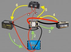
I drew a simplified/stripped down diagram of this specific section of my electro system to represent the heart of my question. Here it is.

Essentially, I want to understand how having a B2B charger and a trickle charger on the same system may or may not present a problem. I am using the equipment in this photo, except for the 12v lead acid battery, the one I have is just your average 12v LA, but not the one in this photo. I have all the correct quality cabling, quality terminals, and all the right fuses etc.
Walking through the diagram:
1. Starter battery ---> orion 18 amp DC - DC.
2. Orion ---> bus bars ---> fuses of hub
3. Hub ---> house battery, charging the house battery. Great. Everything so far is straight ahead.
4. House battery ---> hub.
5. Hub ---> trickle charger (following the manual, trickle charger wired parallel to double the 2.5 amps to 5 amps, as seen in diagram)
6. Trickle charger ---> starter battery
does this create some kind of potential danger of any sort? Manual of the trickle charger states that charger is only charging when the house battery is being charged. This worries me, because the house battery is being charged with the B2B charger, which therefore would allow the trickle charger to charge the starter battery, opening up, to my mind, this electrical loop that I might be more worried about than I need to be. +/- 18 amps passing along the green arrows in the diagram, +/- 5 amps passing along the yellow arrows in the diagram. I am thinking about this like a network of rivers and water, but I think I need to adjust my thinking towards a different and better suited analogy.
I have been making thick battery cables and running all the cables today, my mind is kooky, so maybe I just need to sleep on this and it will make more sense later.
Thank you for any reassurance you could send my way.
I drew a simplified/stripped down diagram of this specific section of my electro system to represent the heart of my question. Here it is.

Essentially, I want to understand how having a B2B charger and a trickle charger on the same system may or may not present a problem. I am using the equipment in this photo, except for the 12v lead acid battery, the one I have is just your average 12v LA, but not the one in this photo. I have all the correct quality cabling, quality terminals, and all the right fuses etc.
Walking through the diagram:
1. Starter battery ---> orion 18 amp DC - DC.
2. Orion ---> bus bars ---> fuses of hub
3. Hub ---> house battery, charging the house battery. Great. Everything so far is straight ahead.
4. House battery ---> hub.
5. Hub ---> trickle charger (following the manual, trickle charger wired parallel to double the 2.5 amps to 5 amps, as seen in diagram)
6. Trickle charger ---> starter battery
does this create some kind of potential danger of any sort? Manual of the trickle charger states that charger is only charging when the house battery is being charged. This worries me, because the house battery is being charged with the B2B charger, which therefore would allow the trickle charger to charge the starter battery, opening up, to my mind, this electrical loop that I might be more worried about than I need to be. +/- 18 amps passing along the green arrows in the diagram, +/- 5 amps passing along the yellow arrows in the diagram. I am thinking about this like a network of rivers and water, but I think I need to adjust my thinking towards a different and better suited analogy.
I have been making thick battery cables and running all the cables today, my mind is kooky, so maybe I just need to sleep on this and it will make more sense later.
Thank you for any reassurance you could send my way.
Last edited:


