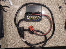
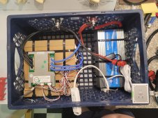
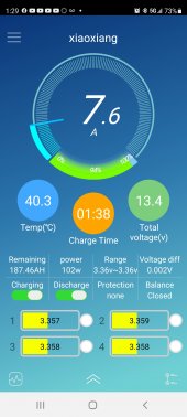
Wow. What a thread this turned out to be! Lots of info to chew on. I took the liberty of unhooking the housing from behind my '18 Ram 7pin and discovered that the main 12V + and Neg wires are 10g, (black and white wires) the rest appear to be 12 and 14. I purchased this 7pin connector w box, and tapped into the 12v leads only, with 8g wire to an anderson connector, and that feeds to my milkcrate 200Ah 4S LFP bank. No trailer, just the milkcrate in the bed of the truck with the cable draped over the tailgate to charge while I drive, for my 1 to 2 day boondock camping purposes. What I found, while monitoring the bms via Bluetooth from in the cab, while on the highway, I'm getting anywhere from 7 to 10A of charging going into the milkcrate from the 7pin. No dc/dc unit involved, just straight 7pin to LFP bank. I figure my bms will offer protection so I don't overcharge, plus, I can still monitor it from in the cab, and turn off the charging switch once I feel its reaching full capacity. I also noticed that when I turn off the truck, while still connected, there seems to be about a 55-60w draw from the LFP. Not sure where that power is going?, back to the truck battery? so I simply turn off the discharge switch while driving, so there's no backfeed of any sort when I arrive at my destination and turn off the truck. Then I unhook the 7pin, enable the discharge switch in the bms, and my milkcrate power bank is ready for use. Am I rolling the dice with this setup? Whats the downside?


")