diy solar

diy solar

DC fuse box location

BMc

New Member
Joined
Feb 20, 2020
Messages
6
I'm new to the forum and a solar newbie, however I'm technically competent. I've not been able to find some answers on the internet and after reading the thread on fusing, I'm hoping you can help me out. I'm building a small house (230 sq ft) and will run 7 10 watt DC LEDs (on 3 circuits) from a 12v battery. I will also have a separate AC system. My original plan was to install the DV fuse box close to the battery and run 6 wires for the 3 circuits to the light switches from there. That distance is approx. 30' using awg 10 wire. However it would be more convenient to run 2 wires from the battery to the 12v fuses mounted next to the AC breaker box and then to the 3 lighting circuits. So my questions are:
Does it mater where the fuse box is located in a DC only system.
What wire size is normal for the battery connections to a DC (solar) fuse box? I'm assuming they're basically the same as uses for autos or marine.
If I do change the location, will I require larger than awg 10 wire for the 12' cable run? Related to my previous question how big are the connection points on a DC fuse box?

Thanks in advance BMc
 
The prevailing wisdom is to have a over current protection device=OCPD within 18 inches of the battery.
MRBF's are a popular solution mrbf example
The idea is to minimize the possibility of a short circuit upstream from the fuse.
Once that is dealt with you are much less contrained where the fuse block goes.
What is the amp rating for the fuse block that you will use.
Most of the DC ones I have seen are 100-125 aggregate and 30 amps per position.
Is that what you have?
 
Fuse box model TBD. It needs to accept AWG 10 at the input connections. Open for suggestions.
I've been looking at one of these: Blue Sea Systems ST Blade ATO/ATC Fuse Blocks
 
Fuse box model TBD. It needs to accept AWG 10 at the input connections. Open for suggestions.
I've been looking at one of these: Blue Sea Systems ST Blade ATO/ATC Fuse Blocks

Blue Sea has a good reputation.
Typically you use crimp on ring terminals for the upstream and spade connectors for the downstream.
Both are available for 10 awg.
 
Should I use two MRBFs for the hot side of the battery? One for the controller and the other for the fuse box?
 
Another option for fuses would be the Mega and Midi type fuses. These come with a variety of fuse holders. I personally use these for my main DC distribution, then use ATO blade fuses for individual circuits.

Your fuse selection needs to be suitable for the cable it is protecting e.g. 10AWG is rated for 52A (according to here) so you obviously wouldn't fuse higher than this. If you only need up to 12A then 16AWG might be suitable with a 15A fuse etc. It might be worthwhile fusing your higher capacity cable with one fuse rating, then each of the smaller cables with something lower.

@FilterGuy did an excellent article recently on fusing considerations.
 
Does it mater where the fuse box is located in a DC only system.

No. It really does not matter where you put your fuse box. Just be sure to put a fuse or breaker at the battery.

What wire size is normal for the battery connections to a DC (solar) fuse box?I'm assuming they're basically the same as uses for autos or marine.

The wire size is entirely dependent on the length of the wire and the amount of current.

Yes, you can use one designed for autos. Sometimes the marine ones have nicer mounting options.

If I do change the location, will I require larger than awg 10 wire for the 12' cable run? Related to my previous question how big are the connection points on a DC fuse box?

Thanks in advance BMc
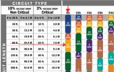
In the fusing thread, there is a link to a slide deck. The last slide has a wire sizing chart you should check out.

You have 7 10W LEDs or 70 watt total. Using Watts law (Power=Volts*Current) we get 70W/12V=5.8 amps
In this case I will use the 1.25 rule 5.8*1.25=7.3 Amps. Always round up, so call it 8 Amps max.

The distance to the Fuse box is 12 feet, but you have to figure the round trip distance (Both the positive and negative) so your distance is 24 feet.

The voltage on the LEDs is not critical so you can use the 6% drop column on the chart.

The chart calls out 14AWG, so your 12AWG would be just fine.

Related to my previous question how big are the connection points on a DC fuse box?
Thanks in advance BMc
That is going to vary from one box to the next, but my guess is that any of them would handle 12AWG with ease.


A bonus suggestion: Mount a few of these in the house.
https://www.amazon.com/Charger-Socket-Waterproof-Delivery-Motorcycle/dp/B07R8JV1LX
 
Should I use two MRBFs for the hot side of the battery? One for the controller and the other for the fuse box?

If you are splitting the wire at the battery (One to the box, one to the controller), then yes, it is best to put a separate fuse on each.
 
Another option for fuses would be the Mega and Midi type fuses. These come with a variety of fuse holders. I personally use these for my main DC distribution, then use ATO blade fuses for individual circuits.

Your fuse selection needs to be suitable for the cable it is protecting e.g. 10AWG is rated for 52A (according to here) so you obviously wouldn't fuse higher than this. If you only need up to 12A then 16AWG might be suitable with a 15A fuse etc. It might be worthwhile fusing your higher capacity cable with one fuse rating, then each of the smaller cables with something lower.

@FilterGuy did an excellent article recently on fusing considerations.
I have a rather unique situation in that the solar system will be relocated to a 2nd house in the future. Current plan based on this input from this tread is to mount the AC breaker box and ATO DC box next to each other, eventually swapping the DC LEDs for AC and moving the wires over to the breakers. The run from the ADO fuse to switch to LEDs is approx. 38ft. I was planning to use AWG 10, but it sounds like 12 gauge will work fine.
 
The run from the ADO fuse to switch to LEDs is approx. 38ft. I was planning to use AWG 10, but it sounds like 12 gauge will work fine.

Keep in mind that when calculating voltage drop, you use the *round trip* length. If the run from the Fuse to switch to LED is 38ft, the round trip is 76ft. (That is getting long for low voltage).

1582435193507.png

I assume each line to the LEDs will be less than 5A so 12AWG from the fuse box to the LED would be OK. However, keep in mind that you will also have a voltage drop from the battery to the fuse box. If you want to be super sure you don't have voltage drop issues, you could go to 10AWG for the higher current line from the battery to the fuse box.... but from what you describe that is optional.
 
Look up tables definitely have their place but the maths is pretty basic - it's all just Ohm's Law (V=IR). The voltage across a conductor equals the current flowing through it multiplied by its resistance. The resistance of copper cable is very well established, tables like this one are quite useful.

For example, 12AWG cable presents 1.58mΩ per foot, 38' there and back is 76', so 0.12Ω in total along the run. At your expected 8A current this would produce a voltage drop of 0.96V (V=IR) and will be dissipating 7.7W continuously (P=I²R) or 185Wh per day. The rule of thumb along any cable run is to avoid more than a 3% voltage drop and for a 12V supply, a 0.96V volt drop represents 8%.

10AWG would produce a 5% voltage drop and dissipate 5W (120Wh/day).
8AWG would produce a 3% voltage drop and dissipate 3W (72Wh/day).

All of these scenarios are safe i.e. 8A is well under the current rating for these cables, you just need to weigh up the disadvantages of higher cost cable to the advantages of reducing power loss (particularly within a battery-powered system).

This is one of the many reasons why high voltage / low current is preferable for solar arrays i.e. reduces resistive losses.
 
p.s. You could, of course, design a 24V system and quarter your losses for the same power.
 
Look up tables definitely have their place but the maths is pretty basic - it's all just Ohm's Law (V=IR). The voltage across a conductor equals the current flowing through it multiplied by its resistance. The resistance of copper cable is very well established, tables like this one are quite useful.

For example, 12AWG cable presents 1.58mΩ per foot, 38' there and back is 76', so 0.12Ω in total along the run. At your expected 8A current this would produce a voltage drop of 0.96V (V=IR) and will be dissipating 7.7W continuously (P=I²R) or 185Wh per day. The rule of thumb along any cable run is to avoid more than a 3% voltage drop and for a 12V supply, a 0.96V volt drop represents 8%.

10AWG would produce a 5% voltage drop and dissipate 5W (120Wh/day).
8AWG would produce a 3% voltage drop and dissipate 3W (72Wh/day).

All of these scenarios are safe i.e. 8A is well under the current rating for these cables, you just need to weigh up the disadvantages of higher cost cable to the advantages of reducing power loss (particularly within a battery-powered system).

This is one of the many reasons why high voltage / low current is preferable for solar arrays i.e. reduces resistive losses.
For my recommendation above, since there are 3 separate light switches, I assumed less than 5 amps for the long runs to the LEDs. I also assumed the LEDs do not have critical voltage requirements so I was not trying to get the voltage drop all the way down to 3%. (if you assume 4 amps for the circuit, it is only around 3.6% for 12 gauge wire)

To be clear there are 3 separate but related things going on.
1) Safety - Can the wire safely handle the current that might go through it.
Fuses or breakers are put in place to put a cap on how much will go through.
Safety will define the minimum size wire to use. Other factors may require larger wires.
2) Voltage drop - How large is the voltage drop between the source and the load to ensure proper functionality of the load.​
  • For some things, voltage can be important to basic functionality and/or longevity. This is where keeping the voltage drop to 3% or less is important and will often requre larger wires.
  • For DC LEDs, voltage is not critical (but can effect the brightness of the LED). In this case you can get away with greater than a 3% voltage drop.
3) Power loss - How much energy are you loosing to the resistance in the wire.​
Most of the time people just live with the power loss once they have safety and voltage drop covered. There are easier ways of reducing loss or adding capacity than over-sizing the wiring. However, selectively choosing higher current lines to over-size can make a reasonable improvement without going crazy with all of the wires. (This is why I sugested the line between the battery and the fuse box might be a place to enlarge the wires)
One more note: Far too often in RVs and sometimes on boats, people assume tying to chassis is sufficient for the negative path on high current circuits and, as a rule, it is not sufficient. You should always run a properly sized negative wire back to the battery.
 
I have a rather unique situation in that the solar system will be relocated to a 2nd house in the future. Current plan based on this input from this tread is to mount the AC breaker box and ATO DC box next to each other, eventually swapping the DC LEDs for AC and moving the wires over to the breakers. The run from the ADO fuse to switch to LEDs is approx. 38ft. I was planning to use AWG 10, but it sounds like 12 gauge will work fine.
If you're putting the wires inside the walls and switch them over to A/C sometime down the road. Then use Romex at the proper size for the A/C circuit or larger. You will want to run 3 wires for the A/C Hot, Neutral, and Ground. You can find it in 14/2, 12/2, and 10/2 and include a Ground wire. At both ends of the runs, leave extra wire for the change over down the road.
 
Back
Top