diy solar

diy solar

dc power is not working properly

hammerhead22!

New Member
Joined
Nov 27, 2021
Messages
14
i am doing this myself and today i connected eveything to my new system and i am having trouble with the dc side of the system. i disconnected the original battery connections at the dc side of the fuse panel. i then connected my new batterys to the panel. the only circuit that works is the second fuse (bathroom light shower light and stove light and fan.) all of the other fuses are fine and so are the wires. i tested the fuse connections and there is no power. what am i missing i am at a loss as to why the connections have no power. i am not an electrician so please if you can help use baby steps.
 
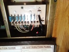
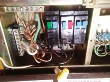
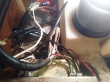
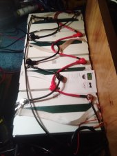
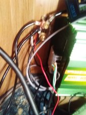
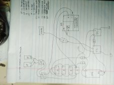
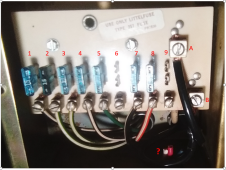
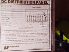
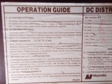
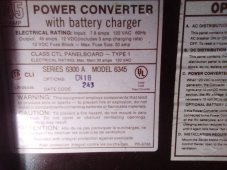
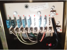
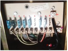
i couldnt figure out how to add a msg. the first pic is the connection to the panel. the 2nd is the ac. the 3rd is the backside where i connected the old negative to the backside of the negative conection in photo 1. (did this after the original connection and it didnt correct the problem) 4th top left is the neg connecyion to the battery and bottom right is the positive. 5th is the shunt and the cable connections (all of my grounds are connected to the same bolt on the chasis)
 
From the description, this appears to be the relevant picture.

1638124829139.png

Several questions:

1) What is 'A' connected to?
2) What is 'B' connected to?
3) Are those the positive wires across the bottom? If so, where do the negative wires for the DC loads connect?
4) What are the two cut wires marked with '?'
5) Are the numbers shown the way you are numbering the fuses? (Is number 2 the working fuse?)

An unrelated observation: I don't know what size inverter you have, but the battery wires sure seem small for a 12V system.
 
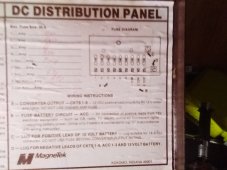
One more thing: It looks like there is a label on the inside of the distribution panel lid. Could you provide a picture of it?
 
A is connected to the positive battery terminal.
B is the negative battery terminal.
yes they are the positives. the negatives are wire nut together which can be seen in the center of pic 3. the original negative wire can be seen going back in at the bottom right and was reconnected to the back of the negative lug.
the cut wires were from the charger
nope number 7 is the only one working. i only counted connected fuses starting from the powerIMG_20211128_141319.jpgIMG_20211128_141320.jpgIMG_20211128_141324.jpgIMG_20211128_141329.jpg
 
i tested the fuse connections and there is no power.
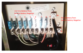
How did you test them? If it is working properly, you should see +12V from one of the connections (Probably the top connection) and battery negative (With no fuse plugged in).

1638127791401.png

Based on what I understand so far either there is something burnt out on the back of the fuse board (unlikely) or there is something wrong with the negative return wires. If you get +12V from one of the fuse connections and battery negative and 0 V between the two fuse connections, it is almost certainly something on the negative side.

If one of your DC appliances on #7 has a negative connection to Chassis, it would still work even if the normal negative path is open.
the original negative wire can be seen going back in at the bottom right and was reconnected to the back of the negative lug.
I suspect something got goofed up when this was done.
 
i used a volt meter and removed each fuse and plugged the positive on top and negative on the bottom and only #7 registered 12+ all the others were 0. i didnt wire this panel it was working before i switched to the new battery set up

i used the old dc neg wire (which was still wired to all those negative dc wires) and reattached it to the back side of the negative lug. could it be in that bundle of wires?
 
i used a volt meter and removed each fuse and plugged the positive on top and negative on the bottom and only #7 registered 12+ all the others were 0
1) On one of the fuses that is not working, try measuring between the connection and battery negative while the fuse is removed. One of the connections should show 0V and the other should show +12V. My guess is that you will find that there is +12V between the top connection and battery negative (The actual battery negative, not the B- lug on the fuse board.).

2) Measure to see if there is any voltage between the B- lug on the fuse board and the negative of the battery bank. If there is a voltage, there is something wrong with the Negative wire going to the B- Lug.

1638130099161.png

Report the results and we will take it from there.
 
Another observation: The current for the DC loads is not going through the shunt. That means the meter watching the shunt will have an inaccurate view of the State Of Charge.

1 tested and i got 0 on the B- and 12+ on the B+ side
2 B- lug and and battery neg 0 reading

Just to be sure we are on the same page, is this accurate?

1638131608224.png
 
nothing connected to #6 tested it and 0 reading i also tested #5 0 reading and b- lug to battery neg 0 reading.


should the battery neg run through the shunt before connecting to the B- lug???
 
i have 3 chassis grounds 1 fron the shunt 1 from the charger and 1 from the transfer switch and they are all connected to the same bolt on the chassis
 
Back
Top