diy solar

diy solar

Design plan - seeking feedback

MilbankAustralia

New Member
Joined
Jul 13, 2021
Messages
18
Hi all,

I'm new here, and this is my first post.

I'm seeking advice about a solar system design for an off-grid cabin.

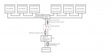
Current equipment plan is as follows:
PhonoSolar PS270P-20/U 270W panels x6, Vmpp 31.44V, Isc 9.09A
SuperSafe SBS 190F AGM 190Ah (10hr rate) batteries x4
EPever TRIRON 4215N 40A controller x2 with temp sensors
Victron MultiPlus-II Inverter Charger 24/3000/70-32

Setup plan:
Batteries setup with 2x series pairs in parallel to make 380Ah 24V bank. Will be installed close to the inverter/charger
3 panels in series to each controller (Vocmax 124.1V, Isc 9.09A). Chassis of each string grounded. Controllers will be installed close to batteries.
Breakers sized to 1.56x Isc between panels and controllers, cables sized to 1.56x Isc.
Solar fuses and cables sized to 1.25x charge current (40A) from controllers to batteries
Breaker between battery and inverter/charger
Will have a generator connected to manually start when solar generation goes down for too long

Questions:
1. Is 80A a suitable charge current from the solar controllers for a 380Ah bank? It is just above 0.2C and I expect the constant load of the fridge to be enough to keep the actual charge rate below 0.2C, which gives lots of wiggle room for adding future constant loads without dipping below 0.1C.
2. Is my sizing of the cables, breakers and fuses correct? 1.56x Isc for the cables and breakers before the controllers, and 1.25x the charge current for the solar fuse and cables from the controllers to the batteries.
3. Am I putting breakers and fuses in the right place and using them appropriately?
- Am I missing any important OCPDs?
- Should I be using fast breaking solar fuses after the charge controllers, or standard DC fuses?
- How do I size the cable and breaker between the batteries and the inverter/charger?
4. What does the 32A rating of the AC transfer switch in the MultiPlus mean? Is it to say that when running with the generator input it can handle a maximum 32A load on the 240V outlet?
5. Is it possible to underutilise the battery storage capacity of a system in a way that is harmful long term e.g only infrequently discharging the batteries to any significant degree? I'm not sure yet what our power use will be because it will depend a lot on greenhouse setups that are yet to be considered. I want to factor in the potential for significantly more constant and intermittent loads than we currently envisage from a fridge, freezer, satellite modem, router, laptop and phone and battery chargers, but want to be sure that using a fairly small fraction of the total storage capacity at least initially won't be problematic for the health of the system.
6. Can I also run a 12V circuit off the batteries? A buck converter in parallel with the inverter/charger to run some 12V sockets from. Can include a voltage sensitive relay to stop draw if the batteries drop below cut-off.
7. Would it be wise to run a BMS with a shunt, or will I get much the same use and battery information from the inverter/charger (which won't include the use from the proposed 12V circuit)?
8. If using aluminium rails to bolt-on mount the panels, is it better to ground the rail directly or to use a grounding lug on each panel chassis and connect the string to ground that way?

My head has been absolutely spinning for the last few weeks trying to figure all of this stuff out and I apologise if I've got everything totally wrong. Certainly not expecting anyone else to do all the legwork for me so if I'm way off feel free to tell me to go back to the drawing board and start over. But any advice (and certainly any reassurance) would be very greatly appreciated. And this part of the plan doesn't include the AC distribution box that will need to be installed.

Many thanks in advance,

Simon
 
Welcome to the forums!

...seeking advice about a solar system design for an off-grid cabin.
  • 6x solar panels in 3s2p configuration - PhonoSolar PS270P-20/U 270W, Vmpp 31.44V, Isc 9.09A
  • 4x 190 Ah (10 hour rate) AGM Batteries in 2s2p (e.g., 24V) - SuperSafe SBS 190F
  • 2x SCC - EPever TRIRON 4215N 40A controller x2 with temp sensors
  • Victron MultiPlus-II Inverter Charger 24/3000/70-32
1. Is 80A a suitable charge current from the solar controllers for a 380Ah bank? It is just above 0.2C and I expect the constant load of the fridge to be enough to keep the actual charge rate below 0.2C, which gives lots of wiggle room for adding future constant loads without dipping below 0.1C.
Check the datasheets to be sure. I've seen some that recommend .1C.

2. Is my sizing of the cables, breakers and fuses correct? 1.56x Isc for the cables and breakers before the controllers, and 1.25x the charge current for the solar fuse and cables from the controllers to the batteries.
Looks like you have 3 panels in series, one string to two SCCs. So, each wire is only carrying 9.09 amps and 3x 31.44V = ~96V.
Size the wire for the application (how much current there will be), and the OCP for the wire.
This thread might help answer other questions: Figuring out how many panels in series and parallel based on your MPPT

3. Am I putting breakers and fuses in the right place and using them appropriately?
I use breakers all over the place, but mainly so I can isolate equipment to work on it. Not sure about where you live, here we need a rapid disconnect system off the roof which can double as a roof-disconnect. Otherwise the minimalist is between the battery and inverter, then OCP for the AC and DC runs.

- Am I missing any important OCPDs?
Sketch out a wiring diagram, look at everything to/from the battery and then check each wire has an OCP somewhere along it's path (preferable as close as possible to the source) that can trip before the wire catches fire.

- How do I size the cable and breaker between the batteries and the inverter/charger?
See What wire gauge should I use? (video, calculator)
In short, the wires must be thick enough to carry the maximum draw of the device (an inverter in your case).

4. What does the 32A rating of the AC transfer switch in the MultiPlus mean?
Not familiar with the device, but that should mean don't try to draw more than 32 amps.

5. Is it possible to underutilise the battery storage capacity of a system in a way that is harmful long term e.g only infrequently discharging the batteries to any significant degree?
Lead acid batteries last longest when they're kept full, most harm is done when the SoC goes below 50% or it's left at low states of charge for extended times. But lead acid is also really finicky and excessive voltage can boil the electrolyte off. So, make sure the SCC settings are appropriate for you batteries and then manually check the voltages in operation to ensure they are what you think they are.

6. Can I also run a 12V circuit off the batteries? ... Can include a voltage sensitive relay to stop draw if the batteries drop below cut-off.
Yes, there are numerous devices available for that ... prices typically vary by the number of amps needed. Just wire it on the far side your 24V low voltage cutoff.

7. Would it be wise to run a BMS with a shunt, or will I get much the same use and battery information from the inverter/charger (which won't include the use from the proposed 12V circuit)?
Hah! Trick questions eh? Lead Acid AGMs don't use a BMS.

8. If using aluminium rails to bolt-on mount the panels, is it better to ground the rail directly or to use a grounding lug on each panel chassis and connect the string to ground that way?
Aluminum conducts, but if coated it might not.... I'd check with the manufacturer's recommendation.

Hope that helps!
 
Many thanks for the thorough feedback Svets.

My questions about wire and fuse sizing were based on some sites about the FEC code, where they mentioned that 'constant' load conductors (including PV supply side and the charging cables) have to be rated to 1.25x the expected max draw, and where PV wiring on the supply side also has to be sized to 1.25x the Isc to accommodate for temperature dependent increases, so 1.56x Isc on the supply side. Just wanted to check if I had interpreted it correctly.

After posting I did see that the inverter actually recommends the size wiring and breakers to connect it to the battery.

Forgive the stupid question about the BMS!

OCPDs on everything - got it. Should the quick break solar fuses be what is used where breakers aren't (i.e between controller and battery for example, as I will be able to isolate the controller with a breaker on the PV side)?

I stumbled down another rabbit hole last night and came across a decent looking EPever all in one unit (UPower UP3000-HM5042) which seems a more cost effective option at the cost of some modularity, using a 48V system.

It only has a single MPPT but for our relatively small array perhaps a single series string is okay, it will be somewhere that isn't shaded at all unless there is cloud. The MPPT operating range is 80-350V though, and 6 of our panels in series still only gets to 180V which is probably only just at the lower end of the optimal operating voltage range. If I went down that avenue, would it be wise to replace the panels we have with a larger series array with a Vmpp close to 350V?

I will have a look for some more decent all-in-one options, and also some other more cost-effective inverter/charger units based around 48V systems too, as this seems the more sensible option if possible?

Thanks again!
 
My questions about wire and fuse sizing were based on some sites about the FEC code, where they mentioned that 'constant' load conductors (including PV supply side and the charging cables) have to be rated to 1.25x the expected max draw, and where PV wiring on the supply side also has to be sized to 1.25x the Isc to accommodate for temperature dependent increases, so 1.56x Isc on the supply side. Just wanted to check if I had interpreted it correctly.
Not sure about the FEC code. Sounds similar to our NEC.

For here, if the ISC is 9.09 amps we first use the solar panel's temperature coefficients to figure out the amps and volts on the coldest expected day. It's usually something like the coldest day in the last 100 years.

That will shift from 9.09 to something higher. The temperature correction calculations are illustrated in Figuring out how many panels in series and parallel based on your MPPT. Your voltage would be 3xVOC for the panels with the temperature correction. Those are the numbers we'd multiply by the NEC factors.

So, next would be to determine the wire type (is for inside or outside, undergound, in a conduit, on a roof, what's the temperature range, etc.). From there you can look up the wire's ampacity to get the correct gauge (not all wire brands have the same ampacity for a given gauge). The gauge should be the next size up to cover I
SCtc. If the wire is on a really hot roof you may need conduit risers (I have them) and you might need to up the gauge again.... see the What wire gauge should I use?

Circuit Breakers usually come in standard denominations (e.g., 10, 15, 20 amps), as long as the breaker protects the wire (i.e., trips at lower or equal to what the wire is rated for yet higher than expected normal current) you should be good. You can get more granular with fuses, but usually you just pick the next size up unless it's very close.

OCPDs on everything - got it.
DC breakers can be expensive (from the forums inexpensive ones are usually junk, be sure they're rated by some authority, e.g., UL, ETL), if you're using it just for maintenance purposes rather than OCP DC switches might be cheaper (again, only buy rated versions).
NOTE: AC breakers are NOT interchangeable with DC breakers and DC breakers may be directional.

Should the quick break solar fuses be what is used where breakers aren't (i.e between controller and battery for example, as I will be able to isolate the controller with a breaker on the PV side)?
Short-circuiting a panel won't hurt it like short-circuiting a battery will, so they don't have to split-second. Important to keep the OCP close to the source as most shorts will be you doing something (e.g., dropping a wrench accidentally), and doing so without a fuse in the path (e.g., across the battery terminals) is bound to cause exciting times you could do without.

The MPPT operating range is 80-350V though, and 6 of our panels in series still only gets to 180V which is probably only just at the lower end of the optimal operating voltage range. If I went down that avenue, would it be wise to replace the panels we have with a larger series array with a Vmpp close to 350V?
Solar panels usually have fairly constant voltage even when clouds go overhead, it's the current that varies. So I don't see problems there.

I will have a look for some more decent all-in-one options, and also some other more cost-effective inverter/charger units based around 48V systems too, as this seems the more sensible option if possible?
Theoretically, 48V should be more efficient than 24V ... but in practice, it depends on the quality of the inverter. If you purchase one of the top of the line systems (e.g., SolArc, Skybox) I'd say sure go 48V. Anything else would require an immense study in the stand-by power consumption, inverter efficiency, usage patterns etc. If you have small and curious kids or are like Electroboom, 24V is marginally safer.
 
Last edited:
Wow Svetz, thanks for the incredibly comprehensive reply.

I think NEC must be what I was referring to.

Thanks for pointing out that I should calculate the temperature compensated PV current output before multiplying for the cable sizing. The value on the panel specs is given as +0.06%/C, which is 9.36 when if the panels get to 75C. The summary you linked explains a lot of the wire derating stuff too, thanks heaps. I'm aware others might apply for buried conduit.

I hadn't realised that the solar source side fuses needed to be compensated to 1.2x for voltage either.

If I instead use a single 40A MPPT controller and put both 3 panel strings into parallel, some stuff I'm reading from an Eaton document and a site referring to NEC stuff seems to suggest that since I only have two strings in parallel, where max Isc is 9.36A x2 which is less than the 20A max series fuse rating of the panels, I don't need fuse each string as long as conductors and the combiners are properly sized, and can then just fuse between the combiner and the charge controller?

Am I interpreting this Eaton document correctly in thinking they are saying to fuse both the positive AND negative cables between the combiner and the charge controller? And these would be sized to 1.2x Voc(max) and 1.56x Isc(tc)? In that case would the fuse on the positive lead be close to the combiner, and the fuse on the negative be close to the charge controller? With the disconnect switch in line between them? And these would be solar fuses? Or do both just go after the combiner? I'm a bit confused about what the negative line fuse is for?

Then there would be a normal DC fuse between charge controller and battery on the positive only, and these do not need the 1.2x compensation for voltage rating but do need to be rated above the max boost voltage of the controller? They should be rated at 1.25-2x the max charge current (under the max cable rating). The manual for the MPPT suggests installing this within 150mm of the battery terminal, which will probably make it closer to the battery side than the controller side?

Then fusing/breaking between the batteries and the inverter/charger as outlined in the model's documentation.

I hadn't considered switches and fuses rather than breakers, thanks for that because the breakers are fairly expensive. And good to know quality can vary a lot.
Solar panels usually have fairly constant voltage even when clouds go overhead, it's the current that varies. So I don't see problems there.
I was curious about this and had read some things to this effect but it is good to have reassurance this is how it works in the real world (and sorry I didn't work out how to do the reply thing until here!)

Theoretically, 48V should be more efficient than 24V ... but in practice, it depends on the quality of the inverter. If you purchase one of the top of the line systems (e.g., SolArc, Skybox) I'd say sure go 48V. Anything else would require an immense study in the stand-by power consumption, inverter efficiency, usage patterns etc.
I went and had a look at the power consumption of the UPower 48V and it is pretty high. ~1.2A. Given we don't need quite that big an inverter in the immediate future I think the plan is to go with the Victron MultiPlus II GX 48/3000/35-32, which is 48V and I can find for the same price as the non-GX model 24V MultiPlus II I mentioned originally. This has a much more reasonable self-consumption and keeps the MPPT separate which I like the idea of in principle. Reliability is also important.

I'm thinking of pairing that with a single EPever XTRA 4415N 40A and running the strings of 3 panels in parallel into this. The panels will all be in the same place and both strings should be exposed to similar enough conditions that hopefully the MPPT can function optimally.

So questions:
- do I need to fuse the strings before the combiner if the combiner is rated >=1.56*Isc(tc)*2 (i.e >=30A)?
- do the fuses between the combiner and the charge controller need to be on both positive and negative leads and if so do they both go on the conbiner side of the DC disconnect switch, or is the negative line fuse to go at the controller end?
- Is 60VDC 50A or 60A the correct fuse to go between the MPPT and battery given the boost voltage and max charge current?
- Does the fuse between MPPT and battery go closer to the battery end or the controller end?

Thanks again for your responses, really helpful!
 

Attachments

  • Solar circuit.png
    Solar circuit.png
    31.6 KB · Views: 9
Wow Svetz, thanks for the incredibly comprehensive reply.

I think NEC must be what I was referring to.
FEC is probably the Australian electrical code, NEC (National Electrical Code) is the U.S. version.

If I instead use a single 40A MPPT controller and put both 3 panel strings into parallel, some stuff I'm reading from an Eaton document and a site referring to NEC stuff seems to suggest that since I only have two strings in parallel, where max Isc is 9.36A x2 which is less than the 20A max series fuse rating of the panels, I don't need fuse each string as long as conductors and the combiners are properly sized, and can then just fuse between the combiner and the charge controller?
Just because your electrical codes say you don't need them doesn't mean you can't put them in. Off the roof here we need some sort of rapid shutdown kill switch. Good idea if it's not in your codes.

Am I interpreting this Eaton document correctly in thinking they are saying to fuse both the positive AND negative cables between the combiner and the charge controller?
I'm not a fan of fusing the negative side if it occurs before grounding (that is I want the system to stay grounded).

I'd write them and ask about it.

Obviously, if either fuse goes current shouldn't be flowing, but it sounds like they're worried about an abnormal case. For example, if the negative fuse goes and the panel and system are both hooked to ground .... then power could still flow across the ground wire.

Perhaps someone else knows?

With the disconnect switch in line between them?
I use breakers as disconnects, perfectly okay here. But your codes might be different. Some folks put a good quality fuse inline with a not-so-great breaker to save money and be safe.

And these would be solar fuses?
I've never heard of a solar fuse. Do they mean a DC fuse?

The manual for the MPPT suggests installing this within 150mm of the battery terminal, which will probably make it closer to the battery side than the controller side?
The battery has the most stored energy, so being closest to the battery is best IMO, not sure if the code has rules around it.

- do I need to fuse the strings before the combiner if the combiner is rated >=1.56*Isc(tc)*2 (i.e >=30A)?
My combiner box has the breaker in it, the wire should be speced for the maximum ampacity plus some, the breaker for less - that is the breaker protects the wire not the devices.

- do the fuses between the combiner and the charge controller need to be on both positive and negative leads and if so do they both go on the conbiner side of the DC disconnect switch, or is the negative line fuse to go at the controller end?
If you've breakers in the combiner box you don't need more.

- Is 60VDC 50A or 60A the correct fuse to go between the MPPT and battery given the boost voltage and max charge current?
If you have 3x 30V panels in series, your voltage should be at least 90V. Size the fuse to protect the wire, if the wire is speced 65 amps, the breaker < 65.

Hope that helps!
 
Svetz I wanted to thank you kindly for your input and advice! Have been out of service at the place so I apologise for the delay.

I've spent a bunch more time reading and looking and am about to post the updated plan with a few questions. You're input greatly helped me get my thoughts in order so really can't thank you enough.

And I meant NEC, just got mixed up.

Cheers!
 
You're going with a Victron inverter ...
Consider a Victron charge controller. With some additional stuff (battery shunt and another Victron device), you can program the battery charge current you want. It will tell charge controller to adjust output current so battery current remains constant while inverter draw varies.

If you do end up with a hybrid/all-in-one, it should already have that feature.
 
Thanks Hedges.

Following on from your point there, this is the new plan:


It uses a Victron SmartSolar and MultiPlus II GX connected via VE.Direct.

Appreciate your input!
 
Back
Top