diy solar

diy solar

Design Review - Growatt SPF 5000 ES Grid Backup & Neutral Bonding

Nice @automatikdonn (y) - looks like #177 video is an implementation of the blind bootstrap method of #161 with clever use of the 2s delayed-on timer within the 240v (and 120v) over/under voltage protection device (for those who may not be familiar with that feature). Even though the delay-on feature of this circuit does cold-start the system, I'm really concerned that there is no stop/failure criteria. That 240v protection relay will continue to send voltage to your 240v loads panel even if the system fails to bootstrap. I think this could be improved by replacing the 240v protection relay with a simple timer board. I dunno about that specific timer board, but I've got a few of these and some of them have like 20+ different built-in functions with user configurable params, and I'm almost certain the blind bootstrap would be satisfied by one of them. Doing so would bound your error and permanently de-energize the AT if bootstrapping failed.

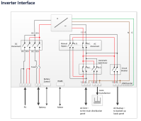
Here's an example of how it'd look, the way I'd do it:
  • GW on-grid. 240v on AC OUT, AT powering 120v loads, all systems go.
  • Grid failure. GW ATS transitions to off-grid. Temporary loss of 240v on GW AC OUT.
  • GW AC OUT comes back online after a couple seconds. Timer circuit is energized by N/C poles of main 240v loads panel contactor (same circuit that powers your 240v over/under protection relay). Timer executes one-shot cold start logic (goes high for ~6s, then goes and stays low), ending the sequence on a logic low, and remaining there as long as it continues to receive 240v from GW AC OUT
This is the system I'd recommend to people who feel the unlikely risk of AT failure is offset by the benefit of a system that automatically starts. Anybody else, I'd recommend human-in-the-loop cold start only.

I personally know I won't be happy until I have the temp sensor of the AT instrumented, so I'm fixin to implement #159. I think this design scales to automated control most elegantly, and right now we have no way I can think of to read the AT thermocouple outside of a 3rd party temp controller or similar. I picked up a chip that converts K-type thermocouples to SPI bus readings. Gonna take some time to integrate to a NodeMCU/etc but if it works I'm happy to open source the code and process. I think this system beats the safety of even human-in-the-loop cold starting, and it's automated.
Yea I agree, I even made sure I said that in the video. This circuit could support a momentary switch easily. You might not need all of the extra when you use a push button though.

We need to find an automated one time switch or programmable method to track the number of bootstrap attempts.

The circuit is really no different than a hard wired direct connect of 240v to the contactor and no safer.

I wanted to mostly show people how easy and flexible contactors are. Maybe even spark an idea on how we solve that one shot issue. I don't know of any way that doesn't involve an externally or battery powered logic controller
 
Yea I agree, I even made sure I said that in the video.

I don't know of any way that doesn't involve an externally or battery powered logic controller
Whoops - I must have missed you saying that. Sorry bout that.

I'm pretty certain we don't need an externally or battery powered logic controller for this. If we view our 'external power' as the 240v AC OUT of the GW, then even if we store bootstraping history/state within any volatile memory of any device, that history is retained as long as our GW AC OUT is supplied. I don't see a condition for that to continuously fail, since GW menu options 6&7 (overload and temp fault, respectively) default to *not* auto-restarting.

I am pretty sure this device, menu option P-35 will work.
1637768944372.png
You'll need a simple wall wart that does 240vac --> 12vdc (or 5v, or 24v), then use that 12vdc to both a) power the board, and b) trigger the board input (at the same time on boot). I'll grab one and test it - the docs are notoriously bad, even translation aside. Always gotta verify experimentally.

While I wait for shipping I'll see if I can get started on the NodeMCU version of the solution.
 
So todays experiment has been interesting so far. I replaced the 220v coil contactors with 120v coil contactors and the switch between shore power and battery power has been seamless. I have switched back and forth 10 times now without a single failure.

Have to go do that turkey day thing, but I thought it would be interesting information to share.
 
Okay next iteration - this one is #152 with the following changes:
  • Uses 120v coil N safety contactor instead of 240v coil contactor (50A 3-pole DIN-mount instead of 40A 2-pole non-DIN mount)
  • Adds electrical momentary cold start switch
This (should) allow electrical actuation of the cold start relay with a momentary pushbutton (option 1 of #152). Note that the cold start relay must be a 240v coil since the only power source available, with the AT off, is the 240v from GW AC OUT. Also note that this momentary pushbutton could be replaced with a wifi switch to allow remote or autonomous cold starting (options 2 & 3 of #152).

One detail is that the cold start button must be at least a 2PDT switch, with one set of N/O and one set of N/C contacts. The N safety contactor coil is routed through the N/C contacts of this switch to avoid closing the N safety contactor during the cold start process (exposing the 120/240v load center to potentially out of tolerance voltage).

The cold start process should look like this:
  • Cold start button pressed. N safety coil de-energized. Cold start coil energized. AT receives power and begins forming neutral.
  • First over voltage protection relay sees L1/N 120v. 2s delay before N is forwarded to second over voltage protection relay.
  • Second over voltage protection relay sees N/L2 120v. 2s delay before L2 is forwarded to the top side of the cold start switch. N safety contactor coil is not energized because its L2 is routed through the cold start switch, which is N/C (so at this point, it's open).
  • Cold start switch button is released
    • Coils of cold start contactor change from being powered directly from L2 of the second voltage protection relay.
    • N safety contactor coils are powered from L2 of the second voltage protection relay via the N/C contact of the cold start switch.
    • System is fully functional (if both voltage protection relays pass tests)
So, in short:
  • Push the cold start button
    • AT is immediately energized
  • Wait 4 seconds
  • Release the cold start button
    • Happy path (both 120v leg pass check):
      • N safety contactor should engage immediately afterward
    • Unhappy path (either 120v leg fails check):
      • AT will de-energize immediately after the cold start button is released
      • N safety contactor will never close, leaving 120/240 loads unpowered
View attachment 73357
I think this will work!
 
Hi, I'm currently putting together a similar system using one GW with AT, with the idea to add another GW in the near future, so watching this thread develop in trying to solve the neutral bonding conundrum has been fascinating. One element that keeps bothering me is the idea that was brought up in post #3 when @USUSUS explained in option #1 how the AT neutral line would be tied in with the grid transformer and how there was probability that the AT would be participating in forming-loads outside the house main service. Is there a way to test if this is in fact happening with the AT when bonded with the main neutral? Perhaps a meter can be placed on the Neutral line to see if current is running through it with no other loads in the main panel or sub-panel on. It just seems odd that someone else's L1 and L2 lines can feed into another's main panel just to get to the AT. Maybe someone can explain this a bit more so I could understand.
 
One element that keeps bothering me is the idea that was brought up in post #3 when @USUSUS explained in option #1 how the AT neutral line would be tied in with the grid transformer and how there was probability that the AT would be participating in forming-loads outside the house main service. Is there a way to test if this is in fact happening with the AT when bonded with the main neutral?
The latest designs, #133 (no AT L1/L2 disconnect), and #159 (AT L1/L2 disconnect + cold start), do not have neutrals connected between the grid and the GW AC OUT. The only time the GW AC OUT neutral is connected to grid is during a grid-down situation, when the N bonding contactor is actuated. At this point, grid neutral has a path to the AT neutral via the grounding conductor run between the panels downstream of the GW AC OUT and the main service panel. Because L1/L2 are switched internally via the GW's internal transfer switch, the only way the grid/AT neutrals would be connected is if both the GW ATS and the internal bonding relay of the GW failed simultaneously.
 
The latest designs, #133 (no AT L1/L2 disconnect), and #159 (AT L1/L2 disconnect + cold start), do not have neutrals connected between the grid and the GW AC OUT. The only time the GW AC OUT neutral is connected to grid is during a grid-down situation, when the N bonding contactor is actuated. At this point, grid neutral has a path to the AT neutral via the grounding conductor run between the panels downstream of the GW AC OUT and the main service panel. Because L1/L2 are switched internally via the GW's internal transfer switch, the only way the grid/AT neutrals would be connected is if both the GW ATS and the internal bonding relay of the GW failed simultaneously.
So if I understand, the designs from #133 and #159 have been a manifestation to solve two main issues using the 5000ES with the auto transformer (Clarify if I get this wrong):
  1. Operating a 120/240v load center with a neutral safety disconnect, should the AT fail.
  2. Finding a way to keep the AT neutral isolated during an on-grid situation with the Growatt.
The first issue I understand, as there is a concern with a failing AT and loss of the neutral line causing an imbalance, but I’m still trying to wrap my head around the second issue. Hypothetically, if the neutral from the AT remains bonded from a subpanel with the neutral of the main ‘grid’ panel, what are the potential dangers that can occur during the Growatt’s on-grid function?
 
I think we're at a pretty good solution for a single GW with #133 and can probably call it a day after conductor/conduit schedules and layout/BOM are nailed down. I think #133 can work for multiple GWs in parallel as well, provided you can limit your 120VAC loads to < 30A.

Re: going overboard on failsafes: I'm not sure exactly what failsafes SolarEdge bakes in, but I do think there's a lot of circuitry that can go overlooked because it resides on a PCB instead of in an electrical enclosure. I agree with you that this post may seem excessive at points, but as an example, I know we're missing the temp sensor portion of the AT (pg 68 of attached pdf, screenshotted below):

View attachment 72692

I've got access to a SE7.6kW with the StorEdge option, so I'll try to make some time to see how it's set up. If anybody else is in a similar situation and wants to compare notes, please do.
Not sure if you guys are still working on this or not but I found the internal wire diagram for Storedge inverters running the Auto transformer. It seems to show that the neutrals are all connected from Main Panel to Sub Panel and the L1 L2 of the AT are switched ON or OFF when running on Inverter or on Grid. Thought this might help as you could wire this with Growatts in the same way using a contactor on the AT that would be operated by the Dry-Contact of the Growatt.
 

Attachments

  • Storedge wiring.png
    Storedge wiring.png
    274.9 KB · Views: 108
Thanks @Trip.Diamond I was wondering about how Solaredge uses their own inverters and how the neutrals are handled. Because if we can eliminate the need to work around the neutral bonding issue, that may simplify the layout similar to post #12.
 
This also seems to imply that providing power to the auto transformer provides an immediate neutral leg, unlike some of the talk here about trying to delay switching on the 120v panel until it was ready in a cold start situation?
 
Hi, I'm currently putting together a similar system using one GW with AT, with the idea to add another GW in the near future, so watching this thread develop in trying to solve the neutral bonding conundrum has been fascinating. One element that keeps bothering me is the idea that was brought up in post #3 when @USUSUS explained in option #1 how the AT neutral line would be tied in with the grid transformer and how there was probability that the AT would be participating in forming-loads outside the house main service. Is there a way to test if this is in fact happening with the AT when bonded with the main neutral? Perhaps a meter can be placed on the Neutral line to see if current is running through it with no other loads in the main panel or sub-panel on. It just seems odd that someone else's L1 and L2 lines can feed into another's main panel just to get to the AT. Maybe someone can explain this a bit more so I could understand.
Which GW are you installing? You might be better served with a pair in parallel from the start instead of installing a single 240V Euro model with auto transformer. Several reasons, one is the N bonding issue, the second is SCC and inverter capacity.
 
Which GW are you installing? You might be better served with a pair in parallel from the start instead of installing a single 240V Euro model with auto transformer. Several reasons, one is the N bonding issue, the second is SCC and inverter capacity.
I'm installing the 5000ES. I would like to install a pair, but don't have the budget at this point. One will serve my purposes for right now as my sub panel will only hold critical loads (i.e. freezer, fridge,...etc.), but the 5000ES seems to be a good option to build upon for the future.
 
I'm installing the 5000ES. I would like to install a pair, but don't have the budget at this point. One will serve my purposes for right now as my sub panel will only hold critical loads (i.e. freezer, fridge,...etc.), but the 5000ES seems to be a good option to build upon for the future.
You would do better with something like this instead, no need for the auto transformer. https://watts247.com/product/hybrid-lv6048-split-phase-120v-240v/

Does 120V and 240V. Can be paralleled later.

Remember if you buy the 5000ES, you have to purchase the auto transformer also. The LV6048 is larger but only has 250V max PV input. If you want 450V PV input, the LVX6048 would work. https://watts247.com/product/lvx-6048-hybrid-solar-inverter-split-phase-120v-240v/

The 5000ES is limited to 5Kw PV input while the LV6048 and LVX6048 are 8Kw (2 seperate inputs of 4Kw)

My current build is with two LV6548's, but you need a pair of them for 240V operation. That is a possible choice for 120V only depending on the load the critical loads panel will have.
 
6kw actually, and not sure how it would react if you went higher. With the high voltage limit and 18A, not sure what would happen if you sent it 6500w or even 7000w. I would be curious. Hope to find out some time.
Actually it is 5500w, I saw it when I looked at the specs before, but ya know how eyes aren't connected to a keyboard.

If you want to know what happens when you overpanel, you need to start here: https://diysolarforum.com/threads/only-offgrid-new-12k-growatt-system-questions.26547/post-394958

and here: https://diysolarforum.com/threads/v...l-specs-of-the-whole-system.11532/post-380819

Both Signature Solar and Watt247 have been telling potential customers they could overpanel. This is incorrect, you will find GW will tell you not to exceed the rated SCC wattage. @kromc5 found out the hard way, now he has to rewire his array plus add more SCC's.

I see way too many newer members watched David Poz's video on the 5000ES plus Signature Solar pushes it. I personally think Signature Solar is doing their customers a disservice by it.

You're talking about an entirely different Growatt inverter. This thread is about the SPF5000ES. Their SPF3500/5000 series has nothing in common with the 12k other than the name Growatt pasted on the front of it. The PV input is 6000w on this model.

What I'm interested in is if you stay within the given max voltage and amperage inputs. Say 380v and 17A - 6460 watt. Both figures are entirely within spec for THIS unit, but are over the 6kw stated input. Would be interesting to see, and I'm not aware of anyone that has tried with THIS unit.
 
Last edited:
You would do better with something like this instead, no need for the auto transformer. https://watts247.com/product/hybrid-lv6048-split-phase-120v-240v/

Does 120V and 240V. Can be paralleled later.

Remember if you buy the 5000ES, you have to purchase the auto transformer also. The LV6048 is larger but only has 250V max PV input. If you want 450V PV input, the LVX6048 would work. https://watts247.com/product/lvx-6048-hybrid-solar-inverter-split-phase-120v-240v/

The 5000ES is limited to 5Kw PV input while the LV6048 and LVX6048 are 8Kw (2 seperate inputs of 4Kw)

My current build is with two LV6548's, but you need a pair of them for 240V operation. That is a possible choice for 120V only depending on the load the critical loads panel will have.
Thanks for the input. I actually looked at those systems as well, but was sold on the growatt for the cost. Ya I know it's a bit of a headache dealing with the auto transformer, but when your on a tight budget in a market where everyone is buying up solar products with long lead times I had to weigh the pro's and con's for my situation. Btw I already have a 5000ES in my possession; bulk of my cash will go to batteries and solar panels.
 
Last edited:
You're talking about an entirely different Growatt inverter.

No, I am referring to the SPF5000 ES.
This thread is about the SPF5000ES.

This spec sheet is for the SPF5000 ES. Max PV input is 5500w. https://watts247.com/product/spf-5000-es/
Their SPF3500/5000 series has nothing in common with the 12k other than the name Growatt pasted on the front of it.

Huh? I'm referring to what occurs when you overpanel any SCC. You're missing the point and how Growatt rates the SCC.

The PV input is 6000w on this model.

5500w, it's on the spec sheet.

What I'm interested in is if you stay within the given max voltage and amperage inputs. Say 380v and 17A - 6460 watt. Both figures are entirely within spec for THIS unit, but are over the 6kw stated input. Would be interesting to see, and I'm not aware of anyone that has tried with THIS unit.
No, that's not how the SCC's are rated. If you actually read the links provided where kromc5 had blown the caps and understood why this occurred, then you wouldn't be thinking of the overpanel. Myself and others have been having the discussion in various threads about what the max PV input is for any of these inverters. After kromc5 blew his up, he contacted Growatt and the response was it was overpaneled, the max is 7000w for that unit. Signature Solar of course now admits it was overpaneled but it seems they aren't covering the mess they created. Don't believe what Signature Solar and Ian at Watts247 might tell you as salespeople, trust the spec sheet and what GW engineers and support tell you.

For the SPF5000 ES, the max PV input is 5500w. If you have 380VOC, the max amps has to be under 14.5a (5500w total) . You can argue the point and even overpanel yourself but someday you will find the magic smoke was let out of the caps. Just because you connect panels in series and get close to the max VOC for the unit doesn't mean you can also run the max amps thru it. It is 5500w, that's it.

Why do you think GW has it in the specs if that is the max input watts? Just so people can ignore it?
 
This spec sheet is for the SPF5000 ES. Max PV input is 5500w. https://watts247.com/product/spf-5000-es/

I don't know where that spec sheet is from, but it must be ancient. I have v1, v2, v3, and v4 of the manual, as well as a current SPF3500/5000 data sheet, and all say 6kw. Believe what you want.
Growatt v1 manual - Page 39

I'm not going to argue the rest, nor was I taking advice from anyone. Just random thoughts. This thread isn't the place to discuss it.
 
Last edited:
I don't know where that spec sheet is from, but it must be ancient. I have v1, v2, v3, and v4 of the manual, as well as a current SPF3500/5000 data sheet, and all say 6kw. Believe what you want.

Yes, I did find an updated spec sheet and it says 6000w.

I'm not going to argue the rest, nor was I taking advice from anyone. Just random thoughts. This thread isn't the place to discuss it.
Everyone thinks they can overpanel and get away with it. Yes, this is a place to discuss it as you injected the subject into this thread. Someone reading it might come to the same idea and think they can overpanel the SCC.
 
Back
Top