diy solar

diy solar

Design Review - Growatt SPF 5000 ES Grid Backup & Neutral Bonding

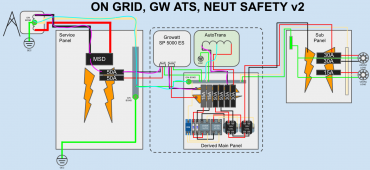
Thanks folks for the feedback - @Desert_AIP I think the situation @LeRoyK proposes does have a current path, but I do agree that L1&L2 ground faults would be clearable on either panel. Here are the fault scenarios I can think of that don't involve loss of conductors (note: fault scenario #3 below is depicted in the attached diagram, with L1 highlighted in pink and N highlighted in bright blue):
  1. Service panel: L1 fault to GND is cleared by double-pole 50A CB in service panel via service panel G/N bond via grid transformer
  2. Service panel: L2 fault to GND is cleared by double-pole 50A CB in service panel via service panel G/N bond via grid transformer
  3. Derived main panel: L1 fault to GND is cleared first by 30A CB in derived main panel via derived main panel G/N bond and grid neutral connection to grid transformer. If 30A CB in derived main panel fails, 50A CB in service panel backs this OCPD up
  4. Derived main panel: L2 fault to GND is cleared first by 30A CB in derived main panel via derived main panel G/N bond and grid neutral connection to grid transformer. If 30A CB in derived main panel fails, 50A CB in service panel backs this OCPD up
Appreciate comments :coffee:
 

Attachments

  • derived_main_panel_fault_scenario_3.png
    derived_main_panel_fault_scenario_3.png
    191.5 KB · Views: 72
In a grid only system,
The primary problem with bonding neutral at multiple points is you turn the ground line into a current carrying conductor because when attached at both ends it becomes connected in parallel to the Neutral.
So even if not shorted to L1 or L2, it would have current flowing through it.

The "ground" serves two functions.
The first is dissipation of induced currents, which is why there is a grounding rod.
The second is the safety "ground" or secondary path to neutral (to complete the short circuit) to trip the breaker if a L1/L2 shorts to the case of a device.

That safety ground is unconnected in the circuit (no complete circuit), unless a ground fault situation occurs, when only connected to the neutral at one point.
---
I would still drive a second grounding rod for the derived panel. It may not be strictly necessary if the derived panel is close to the mains panel, but I don't think it would hurt anything. If that panel is in a detached building (or across a garage on another wall), it definitely needs a separate grounding rod to serve the dissipation of induced current function.

(I deleted the discussion about not pulling a Neutral and bonding at a second point - that was in error based on a scenario I neglected to consider).
 
Last edited:
I rewatched David Poz's video when he installed his three inverters and the auto transformer.
He mentioned someone commented that if the transformer breaker trips there may be an inbalance in the system.

That doesn't make sense.
First, a proper two pole breaker is mechanically connected internally so if one leg trips both legs will shut down, so there should be no imbalance.

(after watching the video I posted later - I understand the concern - not what I was originally imagining)
 
Last edited:
Thanks @Desert_AIP - I'm a little confused on the return path from L1 of the derived main panel in an on-grid scenario. Since our source is the grid transformer, wouldn't we show current on the GN-GN bond link between the service and derived main panels when any 120v load was applied to the subpanel (i.e. in normal operation, and not a ground fault condition)? Would this qualify as objectionable neutral current?

Re: David Poz's loss of neutral, I believe his GW effectively forms a service, and loss of the SE midpoint transformer would entirely disconnect L1/L2 from the AT. The way I understand this, this failure condition causes any branch circuit loads to effectively become a voltage divider with the branch circuits on the other phase.

There are two failure cases:
  1. Loss of neutral with branch circuits on each phase having perfectly balanced loads
  2. Loss of neutral with branch circuits on each phase having imbalanced loads
In the first case, if we lost our AT neutral, we'd see no difference in the operation of our devices. The AT isn't doing any balancing and we see no neutral current.

As an example for the second case, if you had a 50W bulb on one phase, and a 150W bulb on the other (imbalanced phase loads), and lost your AT, you'd see a a voltage difference across the two loads, since they effectively become series loads (a voltage divider) across L1/L2 with no grounded midpoint present.

I did the math for a 50W and 150W example on two branch circuits of the two split phases. If the midpoint transformer is removed, you get a 59.5V drop across the 150W light bulb and a 181.7V drop across the 50W light bulb. With the AT operating, these should of course both be 120V. This neutral failure would manifest as a dim 150W bulb and likely an exploding 50W bulb (effectively becoming a fuse). This is exactly the problem my lost neutral circuits seek to fix.

I'd recommend this video which I think does a great job of illustrating the lost neutral problem. The light bulb example would be the simplest case (one load per phase, purely resistive load). I'm sure this would turn into a nightmare when multiple inductive loads were added in.
 
I'm a little confused on the return path from L1 of the derived main panel in an on-grid scenario. Since our source is the grid transformer, wouldn't we show current on the GN-GN bond link between the service and derived main panels when any 120v load was applied to the subpanel (i.e. in normal operation, and not a ground fault condition)? Would this qualify as objectionable neutral current?
Great point @ususus, We could drive a separate GEC for the 'derived main panel' and not use the GN-GN bond link between the service and derived main panel as you proposed in Post#22 Option#1, this would solve the objectionable neutral current problem. But that leaves us with no safety ground for L1 and L2 between main panel and 'derived main panel'.

I hope you find a good solution to this.
 
The Lost Neutral problem/issue is the same regardless of grid power or derived system.

Is the issue here that we expect it to be a higher probability problem in a derived system than grid?
Because I don't think we spend much time fretting over it in a properly wired grid system with quality components.
A transformer, on grid or derived, is a really simple device with no moving parts.

 
I'll also repost my statement earlier.

The Growatt is essentially an appliance when connected to the grid.
 
The Lost Neutral problem/issue is the same regardless of grid power or derived system.

Is the issue here that we expect it to be a higher probability problem in a derived system than grid?
Because I don't think we spend much time fretting over it in a properly wired grid system with quality components.
A transformer, on grid or derived, is a really simple device with no moving parts.

This video really well put together, thanks for posting, cheers. it helped improve my understanding with a practical demo and diagram with explanation
 
I like @Coty idea of having a dedicated sub-panel for all 120V loads, see post#10. But I think he will still have objectionable neutral current flowing in the ground wire that bonds 120V panel ground to the Main Utility Panel ground.

See attached diagram for my solution to this. I am using @Coty idea of a dedicated sub-panel for 120V loads. The 30A 240V breaker feeding the Auto Transformer guards against the problem of (potentially catastrophically balancing load for other customers) see post#3 Option1.

I would not do a second neutral ground bond in the 120V subpanel, instead, I would connect 120V subpanel neutral to Main service neutral.

I would like to hear your guys' thoughts.
 

Attachments

  • On Grid Growatt Diagram.jpg
    On Grid Growatt Diagram.jpg
    36.6 KB · Views: 76
3tAP6AuTuXmoLLr.png


Curious to hear thoughts on this setup? (Should be nema 14-50, woops)

The Main is connected to service/grid (which means it would be Neutral bonded even when the main is off and interlock is on?)

The idea here is to fully connect the subpanel with inverters + auto-transformer (Like David Poz's setup) to the panel via a plug, so that the 4 lines can be fully connected (when main is down) and fully disconnected (when main is up).

My concern here is the fact the subpanel is bonded. Maybe unbonding this is the way to go? Though I am quite sure the main is neutral-ground bonded anyways.

**This will never run loads on the main panel when the grid is on. Its designed to be a ""backup generator"", not a grid-tie inverter**. Additionally, I plan to charge the batteries via a 240 plug to one of the growatts only. In this case (main is on) the interlock is off, and I'd also unplug the 14-50
 
Last edited:
Thanks @Coty and @Desert_AIP - great info (y)

@Coty - splitting loads into separate panels by 120V and 240V, and limiting the 120V panel to 30A (current limit of the AT) is a very elegant and simple way to do things - great idea. For your information, I believe it is possible to run multiple midpoint transformers in 'parallel' to increase the neutral-forming capacity of a subpanel. Ben's solar and battery (added the link to my first post) is doing this with his sol-ark 12k.

Your idea to limit the 120V panel to 30A feed is great, but I think it may have an issue if the AT fails internally (30A 'main' breaker does not trip, and neutral no longer forms correctly - i.e. one leg shows 180v and the other leg shows 60v...not sure if this is physically possible). In this failure scenario, it seems we'd have an over/under voltage issue that could cause problems.

I reworked my previous design a bit and I think it is a) able to catch that failure mode, and b) allows 240V and 120V loads to be mixed on the same subpanel, since the 120V legs are monitored separately. Downside of my design is that if you 'lose' your AT, you also lose all your 240V loads at the same time.

Updates over the previous iteration (see attached diagram):
  • Moves the neutral safety logic components to the bottom section of the derived main panel to simplify wiring
  • Adds a one-to-many DIN terminal block for the neutral conductor of the neutral safety logic components (simplify wiring)
  • Adds 2A fast-blow fuses to the feeds of the over voltage protection/monitoring circuits of the two AT legs
  • Removes the 50A double pole CB on the AC OUT connection - this isn't needed since all branch circuits are fused, and removal allows use of a more common/cheaper 6-space loads panel
  • Moves the ground-ground bonding between the service panel and the derived main panel from traveling through the Growatt to the ground/neutral busses. This allows calculation of grounding conductor sizing since grounding conductors through the Growatt do not appear to have their ampacities documented
I would think a full disconnect of the system is the most desirable condition. If there is a problem, shut it all down so nothing catches on fire should be the logic when using these types of devices IMO. Let me know how it works out, I have the same system.
 
I was thinking it could work something like this. I am not sure if this is electrically sound or not, but the purpose is to detect a neutral fault by using a contactor that would cut all legs in a downstream panel. It is the only way I can think of how to automate the mitigation of a fault by the neutral leg. I will be able to say for sure in a few days if it works as expected. (if amazon actually delivers on time)

Contactor is here

Wiring for Growatt 5000ES with Neutral disconnect.png
 

Attachments

  • Wiring for Growatt 5000ES with Neutral disconnect.png
    Wiring for Growatt 5000ES with Neutral disconnect.png
    879.1 KB · Views: 26
Last edited:
I was thinking it could work something like this. I am not sure if this is electrically sound or not, but the purpose is to detect a neutral fault by using a contactor that would cut all legs in a downstream panel. It is the only way I can think of how to automate the mitigation of a fault by the neutral leg. I will be able to say for sure in a few days if it works as expected. (if amazon actually delivers on time)

Contactor is here

View attachment 70446
The 120V coil on the contactors usually has a pretty wide operating voltage, I am guessing it will not disconnect even if you turn off the 30A breaker feeding the Auto Transformer. watch the video that @Desert_AIP posted.

When testing, be sure to only use loads like light bulbs, that you don't mind destroying, be sure to put a 120 load on both Black and Red legs when testing. I am curious to see how low that the voltage between Black and Neutral needs to be before the contactor will turn OFF. If the voltage goes higher than 120V between Black and Neutral then I do not expect the contactor to turn OFF.
I was looking at this device to ensure the voltage stays in a specified range to power the contactor. I wish they had more options, but this looks like it will do the job. As talked about earlier in the other diagrams I will need some form of voltage monitoring circuit to make sure it stays in range and if not it will kill the contactor. You are completely right that there needs to be overvolt and undervolt protections built into the contactor circuit. The only reason I am pretty much rehashing this whole topic is because the ideas were solid, but I didn't see any links to any products - so I was hopeful to get some eyes on what I was looking at to build out what has been drawn in all of the available charts in this thread.

I have a 15kw Growatt system with two autotransformers to power my house and shop (I may need more, but this system seems to scale well), so I want to make sure my logic is solid and makes sense before I get too far down the road.

Thanks for any replies, I know everyone has normal day jobs and finding time to look at all of this stuff doesn't always fit into everyone's schedule.

So far I have this contactor

And this undervolt / overvolt protection relay


The rest should be locally sourceable.
I like this, If you add voltage monitoring then your diagram is looking great!
 
I was looking at this device to ensure the voltage stays in a specified range to power the contactor. I wish they had more options, but this looks like it will do the job. As talked about earlier in the other diagrams I will need some form of voltage monitoring circuit to make sure it stays in range and if not it will kill the contactor. You are completely right that there needs to be overvolt and undervolt protections built into the contactor circuit. The only reason I am pretty much rehashing this whole topic is because the ideas were solid, but I didn't see any links to any products - so I was hopeful to get some eyes on what I was looking at to build out what has been drawn in all of the available charts in this thread.

I have a 15kw Growatt system with two autotransformers to power my house and shop (I may need more, but this system seems to scale well), so I want to make sure my logic is solid and makes sense before I get too far down the road.

Thanks for any replies, I know everyone has normal day jobs and finding time to look at all of this stuff doesn't always fit into everyone's schedule.

So far I have this contactor

And this undervolt / overvolt protection relay


The rest should be locally sourceable.
I think you still need to add an N/G bond somewhere for Off-Grid Inverting mode.
I would prefer to do it by connecting your 'Solar Disconnect Service Panel' Neutral to the 'Main service Panel' Neutral so that you only have one N/G bond in the system. If you add a second N/G Bond then there is potential for Objectionable current in the ground wire between 'Solar Disconnect Service Panel' and 'Main service Panel'. See @ususus post #28
I'm a little confused on the return path from L1 of the derived main panel in an on-grid scenario. Since our source is the grid transformer, wouldn't we show current on the GN-GN bond link between the service and derived main panels when any 120v load was applied to the subpanel (i.e. in normal operation, and not a ground fault condition)? Would this qualify as objectionable neutral current?
 
+1 on needing a N/G bond in your 'solar load service panel' of post #37 @automatikdonn - right now it looks like your setup would not be able to clear a ground fault due to the lack of that N/G bond.

It also looks like we're doing the same thing with a lost neutral failsafe, our components look functionally equivalent except you're disconnecting three poles (L1/L2/N) and I'm disconnecting two (L1/L2). See 'OVER VOLTG' components in the 'Derived Main Panel' of post #13.

The under/overvoltage protector relay you spec'd is the same one I was thinking, however it has a minimum disconnect time of 0.1s. Not sure if that'd be fast enough to save a device from going up in flames in the event of a lost/out-of-spec neutral/AT.

One other thing I want to make people aware of is that the GW ES5000 has a setting (setting #24) that allows conditional switching of the dry contact relay in the inverter unit when going from on to off grid states. What this gets us is the ability to conditionally bond our subpanels when we transition to off-grid. This seems unnecessary IF the AT balances all subpanel loads in both on and off-grid cases. Correct me if somebody sees a use for this that I don't.

Finally - @LeRoyK I think I may have a misunderstanding of current flow within a midpoint transformer in my comment about objectionable neutral current in post #28. I believe that neutral current wouldn't be between the AT and the grid transformer, but rather between the AT N and the 120V N load. If so, we wouldn't see neutral current on the G/N - G/N bond link between our service panel and main derived panels.
 
Finally - @LeRoyK I think I may have a misunderstanding of current flow within a midpoint transformer in my comment about objectionable neutral current in post #28. I believe that neutral current wouldn't be between the AT and the grid transformer, but rather between the AT N and the 120V N load. If so, we wouldn't see neutral current on the G/N - G/N bond link between our service panel and main derived panels.
How does the 120V N load current decide which Transformer to use? Being that the Grid Transformer and the Auto Transformer are in parallel.
 
I think you still need to add an N/G bond somewhere for Off-Grid Inverting mode.
I would prefer to do it by connecting your 'Solar Disconnect Service Panel' Neutral to the 'Main service Panel' Neutral so that you only have one N/G bond in the system. If you add a second N/G Bond then there is potential for Objectionable current in the ground wire between 'Solar Disconnect Service Panel' and 'Main service Panel'. See @ususus post #28
Is the ground disconnected in Off Grid mode? I don't actually have these interters operational just yet, so I can't really check mine.

Just so I am understanding the logics of the concern with the circuit, when in offgrid mode - the Solar Disconnect Panel becomes the Main Service panel as a SDS in which case it needs a neutral ground bond? Did I understand that correctly?

If that is the case for concern, there needs to be a mechanism to properly and fully disconnect the main service entrance to the Inverter and connect a neutral bonded ground for this to be 100% automated.
 
+1 on needing a N/G bond in your 'solar load service panel' of post #37 @automatikdonn - right now it looks like your setup would not be able to clear a ground fault due to the lack of that N/G bond.

It also looks like we're doing the same thing with a lost neutral failsafe, our components look functionally equivalent except you're disconnecting three poles (L1/L2/N) and I'm disconnecting two (L1/L2). See 'OVER VOLTG' components in the 'Derived Main Panel' of post #13.

The under/overvoltage protector relay you spec'd is the same one I was thinking, however it has a minimum disconnect time of 0.1s. Not sure if that'd be fast enough to save a device from going up in flames in the event of a lost/out-of-spec neutral/AT.

One other thing I want to make people aware of is that the GW ES5000 has a setting (setting #24) that allows conditional switching of the dry contact relay in the inverter unit when going from on to off grid states. What this gets us is the ability to conditionally bond our subpanels when we transition to off-grid. This seems unnecessary IF the AT balances all subpanel loads in both on and off-grid cases. Correct me if somebody sees a use for this that I don't.

Finally - @LeRoyK I think I may have a misunderstanding of current flow within a midpoint transformer in my comment about objectionable neutral current in post #28. I believe that neutral current wouldn't be between the AT and the grid transformer, but rather between the AT N and the 120V N load. If so, we wouldn't see neutral current on the G/N - G/N bond link between our service panel and main derived panels.
Yes, I was pretty much cloning your design, but in a way I can make my own docs (I use lucidchart)

>+1 on needing a N/G bond in your 'solar load service panel' of post #37 @automatikdonn - right now it looks like your setup would not be able to clear a ground fault due to the lack of that N/G bond.

I am trying to understand the current flow and why that is. Is there anyway we can collaborate on a drawing so people can see all of the failure modes and protection mechanisms that can be put in place to handle those failures.
 
Back
Top