diy solar

diy solar

Designing my first solar system for my van. Please critique my diagram.

Ganbatte

New Member
Joined
May 31, 2023
Messages
18
Location
USA
Hello All,

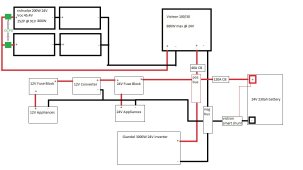
I have no experience with solar, but have been watching lots of videos and doing a lot of reading here on the forum and elsewhere. I am designing a system for my camper van. I expect to consume up to 3000wh/day but more like 1500wh most days. So the battery is sized to store excess capacity for cloudy days, and higher use days. The van will mostly be used in the southwestern US April - September, and any possible winter time use would be in Mexico or further south. The largest load I expect to put on the system is an induction cooktop that can draw 1800W, though I don't expect to be using both burners on full blast very often.

Please take a look at my diagram and tell me what you think. Any suggestions and/or guidance is very much appreciated!
 

Attachments

  • Solar ver 3.jpg
    Solar ver 3.jpg
    96.3 KB · Views: 40
Last edited:
I would move the victron negative cable to the same point as the rest for even charging.
 
Put a shunt based battery monitor on your system- such as a Victron Smartshunt or BMV712.

Are you putting eight 220ah 24v cells - that would be about 2000ah @ 24v. That is a MASSIVE battery for a van. Or is your drawing indicating incorrect and you are putting in a eight 230ah cells making one battery at 24v.

If working with many batteries- the best way to connect is each battery goes to a bus bar with exactly the same length and size cable. One easy way (not necessarily the cheapest) is to use a Victron Power In (or two in your case of eight batteries). Then have the shunt and battery switch - you could then use another Power In (add fuses to make it like a Distributor- see YouTube for how to do that), your inverter, mppt, and 24v stuff connect to that nicely fused.

Also, so since you have other Victron items - get the Cerbo and touch. Watch a few YouTube’s and you will understand why.

I think you may have too big of a battery for a Van. If you add a Victron Dc-Dc charger 12/24 non-isolator charger, you can use your alternator to help charge the lithium battery bank. (My guess is four batteries is way too much).

Space is your MOST precious resource in a Van.

Good Luck!
 
Sorry for the confusion, it's one 24V 230ah battery - about 5,500wh. I'll change the diagram to reflect that more clearly.

I'm planning to build my battery with the overkill BMS. Would that fill the same role as the shunt based monitor?
 
Your diagram needs all the positives and negatives flipped for every other cell - to indicate a series battery. I think that size of battery will be ideal for a Van.

Find some bus bars and put those in the system on the 24v side - Blue sea makes good ones (you will need two) - Victron PowerIn(add fuses) is awesome (but expense and big).

The overkill bms will give a good guess of capacity- but the Smartshunt is much more accurate. If you are going with a complete Victron setup - it is necessary (watch a few YouTubes on the Cerbo. If your inverter is a Victron inverter- go all out Victron (the Cerbo controls parts of the inverter). Do you have an inverter/charger (such as a Multiplus) or just an inverter?

. I would recommend somehow having a 120v charger (either built in to the inverter or separate). That way if your batteries are low you have the option of finding a RV park with power (or Moochdock at a friend/relative) and in the morning your battery will be 100% full.
 
Here's the latest version. I added the smart shunt, and some busses, upped the main CB to 160 amps for inverter load, and decided on a Giandel 3000w unit. I looked into inverter chargers, and for the price and size I don't think it's worth it for me. If I decide in the future I need to be able to charge from grid power, I'll add a dedicated charger.

Regarding over current protection for my array, I'm reading that it's not necessary for 2S2P provided the source cables are rated for 156%isc and output is rated for 2 x 156% isc. Is that correct?

next i'm going to go through and spec all the correct wire sizes for each connection, and figure out all the different connectors/terminals I'll need.
 

Attachments

  • Solar ver 4.jpg
    Solar ver 4.jpg
    85.7 KB · Views: 12
latest version with wires sized. Am i missing anything? I feel like I'm ready to start spending money...
 

Attachments

  • Solar ver 5.jpg
    Solar ver 5.jpg
    99.2 KB · Views: 16
Would like to point out that since you upgraded to the 3000W Giandel, carry the 2/0 wire all the way to it.
You also need a fuse at the positive busbar to the 24v fuse block.
Your negative cables on the appliance side should also be 6 AWG.
A 20a CB on the panels main positive would be a handy disconnect when working on the solar array/SCC.
Looks like a good start. ?
 
Thanks for you suggestions. I added breakers on the appliance circuit and panel circuit, and upgraded the inverter leads to 2/0. I also changed the wiring to reflect that the fuse blocks have their own ground bus for the appliances they power, which will simplify things.

Right now I'm not going to install the 12V part of the system. I've been shopping around for all the appliances I'm going to connect, and everything is available in 24V.
 

Attachments

  • Solar ver 6.jpg
    Solar ver 6.jpg
    105 KB · Views: 10
91Voc array for a Victron 100/30 is too close for use in the USA. That Voc is rated at 25C (77F) and as the temperature drops the voltage increases. If your panels get close to freezing (can get a real temp calc if you provide panel temp coefficient), the array will exceed 100V and probably let the magic smoke out of your SCC.
 
Shoot, and I just ordered the 100/30. So I should go with the 150/35 then? Here are the coefficient numbers for the panel. How do I use these to determine the change as the temperature drops?

Temperature Coefficient of Pmax0.21667 %/°C
Temperature Coefficient of Voc0.16111 %/°C
Temperature Coefficient of Isc0.02778 %/°C
 
Well, I'm a full time nomad and I tend to avoid the cold but I'd like to be able to handle some cold conditions on occasion.

I found the paper in the resource section on adjusting panel VOC for temperature. I'm calculating a 3.6V increase at 0C. It seems I can go all the way down to -35C (-31F) before I hit 100V. Is that correct? The paper says most panels have a Voc coefficient between .2 and .4 with newer panel designs being on the lower end of the spectrum. Does .16111 for my panels sound unrealistic? Or maybe because these aren't a full size panel? I found those coefficient numbers here. Not sure how accurate they are. Also sent an email to richsolar, but they're closed for the weekend.
 
45.5Voc x 25C delta x .00161 = 1.8 deg C change.

Yep, that is an unusually low temp coefficient, its usually between .3 and .4 from my experience.

If you get to extremely low temps you can just disconnect your array (or switch to 2P temporarily).
 
Good idea about switching to 2P. I assume I can monitor voltage real time through the victron app.

I'll wait to see what richsolar says to make sure that number is correct. I searched around a bit more, and learned that the coefficient is per diode, and goes up as more diodes are put in series. So if .16111 is correct perhaps it is because it's not a full sized panel. This is also a 9bb panel which is apparently a fairly new thing that brings all sorts of improvements though I haven't found any info specifically about Voc coefficient. I'll update once I hear back from richsolar.
 
Good idea about switching to 2P. I assume I can monitor voltage real time through the victron app.
Where folks normally run into temp related voltages is early morning, BEFORE the SCC starts charging. Without the SCC pulling any current, the panel voltage is open circuit. Once the SCC starts pulling current, the voltage is near Vmp and normally not a problem.
But, it can also happen mid day with clouds rolling in and out.
 
Rich Solar got back to me. Here is a link to their spec sheet. It lists coefficient of Voc as -0.39%/F which is -0.70%/C. Yikes, that's bad! So I'm wondering if it's a typo and should be celcius rather than fahrenheit. I wrote them back asking them to double check. We'll see what they say.
 
Rich Solar confirmed that the spec sheet is incorrect, and all of the temperature coefficients should be in celcius. So the correct coefficient for my panels is -0.39%/C. Better, but still too close for comfort as at 0C that puts my system voltage at 99 and change. I went ahead and returned the Victron 100/30 and a 150/35 is on the way. Thanks MisterSandals for catching the problem before it became a problem!
 
Back
Top