diy solar

diy solar

Designing Victron System for Keystone RV Travel Trailer

The BMS can also measure the SOC and other parameters identical to the smartshunt. So why not keep the money in your pocket from the shunt and use the BMS information. This can also be connected to the GX device so you can read the SOC. This can be either the Cerbo or the multiplus. If it doesn’t work as you wanted then install the smartshunt later on.
Personally, I had problems with wildly fluctuating current readings in the BMS (both Daly and JK) while using an 230V inverter/charger, this caused the BMS SOC reading to be incorrect.

Luckily, the Victron shunt solves this and I can monitor the battery using the Cerbo GX and the shunt.
 
Last edited:
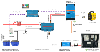
Can't thank you guys enough for the help. Here's the V5 schematic:
Schematic v5.PNG

Personally, I had problems with wildly fluctuating current readings in the BMS (both Daly and JK)
Thanks for the heads up. Gonna risk going with no shunt to start and see how the BMS does by itself. I'll capacity test with a current clamp and compare results. If i need to add a shunt later it'll be a quick fix.
There is a jbd with a 200amp contactor.
I think this is the one you you're talking about?
 
The Orion you have in the latest design is certainly the "big dog" from Victron. Since you have a travel trailer, as opposed to a fifth wheel, I doubt you'll ever need the 70 amps that the Orion can produce. The 50 amp fuse downstream of the Orion would normally be considered undersized, but you're unlikely to use more than the fuse's rating. I have 6 gauge running into my RV's main distribution panel. I think that was the largest I could fit into the terminal. I did use a ferrule on the cable in that terminal.

When you add solar, the solar charge controller will also have an equipment ground. You might want to consider a ground bus bar to consolidate all the equipment grounds. That way you have a single cable going to the frame. That's what I did, just to make the install easier and cleaner.
Since the downstream wire is 6 awg you could bump the maxi fuse up to 80 amps.
 
The Orion you have in the latest design is certainly the "big dog" from Victron. Since you have a travel trailer, as opposed to a fifth wheel, I doubt you'll ever need the 70 amps that the Orion can produce.
Good to know. I'll switch to the 40A Converter in that case and save some $$.

When you add solar, the solar charge controller will also have an equipment ground. You might want to consider a ground bus bar to consolidate all the equipment grounds. That way you have a single cable going to the frame. That's what I did, just to make the install easier and cleaner.
Good call. So the ground coming off the power-in negative side go to a ground bus bar, along with any equipment grounds, then that would go to the frame?

Since the downstream wire is 6 awg you could bump the maxi fuse up to 80 amps.
Worth bumping up the fuse size if I downgrade the converter to 40A? It doesn't look like that converter is fused and I'm not seeing anything on the datasheet about if it needs to be protected from over-current.
 
Worth bumping up the fuse size if I downgrade the converter to 40A?
I don't think you should downgrade.
I also don't think it will save any significant money.
It doesn't look like that converter is fused and I'm not seeing anything on the datasheet about if it needs to be protected from over-current.
The wire needs to be protected.
 
Also the 70 amp unit has studs and the lesser units have faston connectors which suck.
 
I don't think you should downgrade.
I also don't think it will save any significant money.

The wire needs to be protected.

Thanks. Purchased the cells and BMS last night on Cyber monday pricing, so looks like this is happening. ?

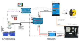
Schematic v6.PNG
 
SendIt, I don't know your trailer. Mine is a toy hauler and I can put some significant stress on my DC system with all the toy hauler related stuff like compressor, larger water pump, fuel transfer pump, etc. I doubt that I would hit 70 amps, but I bet I could hit 30 easy if I ran more than a couple things at the same time. There's also the thought that a 70 amp device run at no more than 40 amps will outlast a 40 amp device ran at 40 amps.

Also keep in mind how much room you have for all the components. I created a CAD drawing of my compartment so I knew that everything would fit. The layout looks great, right up until you add all the cables, then it goes to hell. Cables that make tight bends are critical when the components are in a small compartment.
 
typo in schematic, had the old bms. Went with the contactor @John Frum recommended:
Schematic v7.PNG
SendIt, I don't know your trailer. Mine is a toy hauler and I can put some significant stress on my DC system with all the toy hauler related stuff like compressor, larger water pump, fuel transfer pump, etc. I doubt that I would hit 70 amps, but I bet I could hit 30 easy if I ran more than a couple things at the same time. There's also the thought that a 70 amp device run at no more than 40 amps will outlast a 40 amp device ran at 40 amps.

Also keep in mind how much room you have for all the components. I created a CAD drawing of my compartment so I knew that everything would fit. The layout looks great, right up until you add all the cables, then it goes to hell. Cables that make tight bends are critical when the components are in a small compartment.
In a past life I spent 30+ hours a week in SolidWorks... I'll probably CAD it all up before purchasing, but on the back of en envelope I think I can get it all in there. The wire runs are always a lot more space than you expect and modeling them with splines is a pain in the butt. Worst case scenario I can move everything under the bed and increase the 24V run to ~17 ft. Don't think it'll come to that though.
 
SendIt, I don't know your trailer. Mine is a toy hauler and I can put some significant stress on my DC system with all the toy hauler related stuff like compressor, larger water pump, fuel transfer pump, etc. I doubt that I would hit 70 amps, but I bet I could hit 30 easy if I ran more than a couple things at the same time. There's also the thought that a 70 amp device run at no more than 40 amps will outlast a 40 amp device ran at 40 amps.

Also keep in mind how much room you have for all the components. I created a CAD drawing of my compartment so I knew that everything would fit. The layout looks great, right up until you add all the cables, then it goes to hell. Cables that make tight bends are critical when the components are in a small compartment.
I think it was @Lt.Dan who confirmed that the 70 amp victron dc2dc converter fits in the same space that the legacy wfco ac2dc converter occupied.
 
typo in schematic, had the old bms. Went with the contactor @John Frum recommended:
View attachment 122231

In a past life I spent 30+ hours a week in SolidWorks... I'll probably CAD it all up before purchasing, but on the back of en envelope I think I can get it all in there. The wire runs are always a lot more space than you expect and modeling them with splines is a pain in the butt. Worst case scenario I can move everything under the bed and increase the 24V run to ~17 ft. Don't think it'll come to that though.
The only run that is an issue will be to the dc distribution center.
From memory I think most of the dc distribution panels accept up to 4 awg.
 
I just noticed that in the new drawing you show the multiplus 2 grounding lug connected to the frame.
I suggest you connect that to the lynx negative.
Bond the lynx to the frame so there is only one connection to the frame.
The reason to do this is a dc ground fault inside the mp2 chassis is lot of current over a non-deterministic path.
Makes sense.
 
Just did a quick skim through your thread here and only have one question: Does you trailer have a leveling system or electric/hydraulic jacks? This was a big problem with my RV. I even used a 100a 48v to 12v converter and it still wasn't enough (constant amp draw from the system was only 65~ amps, but the starting surge was way too much).

I ended up removing the converter, installing a small 75Ah AGM battery to take the surges, and then used a much more cost effective 20a Victron IP22 to keep the AGM battery topped off. Never had a problem since then, and the 20a is plenty, even for my very large/power hungry 5th wheel.

I also work in Solidworks for 6+ hrs a day for work, and I put my entire compartment in CAD, with all the related parts. It was quite awesome. After designing it, I was able to make all the mounting brackets, the drop floor for more space, and everything already had mounting holes and wire routing planned. Worked very well!
inverter-bay-png.53262
 
Back
Top