There are very few travel trailers that have a leveling system. Heck, very few of them have powered leveling jacks, but that's changing. I assumed that the OP's trailer had none of that, but it's a good question to ask.
You are using an out of date browser. It may not display this or other websites correctly.
You should upgrade or use an alternative browser.
You should upgrade or use an alternative browser.
Designing Victron System for Keystone RV Travel Trailer
- Thread starter SendIt
- Start date
Lt.Dan
Solar Wizard
I agree. I am seeing more and more of the newer ones having electric scissor jacks, and not full systems. But can't hurt to ask!There are very few travel trailers that have a leveling system. Heck, very few of them have powered leveling jacks, but that's changing. I assumed that the OP's trailer had none of that, but it's a good question to ask.
Victronenergy.com has a lot of system schematics for trailers and mobile wiring, with a lot of information. Just go to victronenergy.com, downloads, system schematics, multi plus , US van drawings. The schematics are more than you may need but it shows grounding and bonding for a mobile unit. If you enlarge the drawing there is a large amount of details and notes that may help you. Good luck.
Updated schematic with grounding and shunt removed:
View attachment 121935
Gonna sit on it a bit before purchasing anything. The trailer is currently in storage and I can't remember, but am pretty sure that the A/C components are grounded to the frame in multiple places. I found manufacturer instructions on how to do a g-n bond in my generator.
Thanks again for the input.
Are you going for a champion Geno ? I've heard BAD things
Thanks for looking it over. I've got manual scissor jacks all four corners and I just use an 18V impact gun toJust did a quick skim through your thread here and only have one question: Does you trailer have a leveling system or electric/hydraulic jacks?
Very cool! I do miss it sometimes... well not optimizing for large assemblies, but parametric modeling haha. I no longer have access to a license, so I haven't figured out what program i'm going to use for this project.I also work in Solidworks for 6+ hrs a day for work, and I put my entire compartment in CAD, with all the related parts. It was quite awesome. After designing it, I was able to make all the mounting brackets, the drop floor for more space, and everything already had mounting holes and wire routing planned. Worked very well!
I've owned it for a few years and gotten a decent amount of use out of it. So far no issues ?Are you going for a champion Geno ? I've heard BAD things
Thanks for looking it over. I've got manual scissor jacks all four corners and I just use an 18V impact gun toannoy everyone within 3 mileslevel the trailer by hand.
Minor FYI, the impact gun will eventually round off the bolt on the jack. I learned this the hard way. I now use a cordless drill, I just have to set the clutch so it doesn't break my wrist.
Lt.Dan
Solar Wizard
For my personal drawings, I bought Solidworks for Makers. Its 100% solidworks, and only $100/year! Its a little complicated to get setup and how to get it open because of the stupid way they do it. I got flustered a few times, but I got it figured out. For $100/year, I couldn't complain lol.Thanks for looking it over. I've got manual scissor jacks all four corners and I just use an 18V impact gun toannoy everyone within 3 mileslevel the trailer by hand.
Very cool! I do miss it sometimes... well not optimizing for large assemblies, but parametric modeling haha. I no longer have access to a license, so I haven't figured out what program i'm going to use for this project.
The only bummer about it, is you can only open Solidworks Maker files with Solidworks for Maker. If you send it to someone with a full license, it won't let them open it. Part of the reason why its only $100. But Solidworks for Maker can open any Solidworks file from any version.
Not a bad deal, especially considering I wouldn't have to learn a new tool. Thanks for the tip.For my personal drawings, I bought Solidworks for Makers. Its 100% solidworks, and only $100/year! Its a little complicated to get setup and how to get it open because of the stupid way they do it. I got flustered a few times, but I got it figured out. For $100/year, I couldn't complain lol.
Hello,
I've finally got all my parts in and brought the trailer out of storage to get everything wired up.
I took a look at the existing grounding setup in the trailer, and there are two places where electrical is grounded to the frame via a bolt:
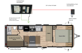 Given that my new battery and equipment is going to be some distance away from the power distribution and existing ground there, what makes more sense?
1. Run a ground from the new equipment to the existing shared ground at the power distribution panel
2. Create a new ground for the battery like the current system does
I'm installing my new battery and equipment in the area where the double bunks are in the image above. The power distribution is under the refrigerator, so there's a 8-10' wire run to the existing ground from the new equipment. I'd like to avoid buying 8' of 2/0 to tie into the existing ground if it's not necessary. Here's an updated schematic with the wire runs a little more apparent. Is it a problem to have a second chassis ground by the new battery, like the existing system does?
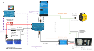
Thanks!
I've finally got all my parts in and brought the trailer out of storage to get everything wired up.
I took a look at the existing grounding setup in the trailer, and there are two places where electrical is grounded to the frame via a bolt:
 Given that my new battery and equipment is going to be some distance away from the power distribution and existing ground there, what makes more sense?
1. Run a ground from the new equipment to the existing shared ground at the power distribution panel
2. Create a new ground for the battery like the current system does
I'm installing my new battery and equipment in the area where the double bunks are in the image above. The power distribution is under the refrigerator, so there's a 8-10' wire run to the existing ground from the new equipment. I'd like to avoid buying 8' of 2/0 to tie into the existing ground if it's not necessary. Here's an updated schematic with the wire runs a little more apparent. Is it a problem to have a second chassis ground by the new battery, like the existing system does?

Thanks!
John Frum
Tell me your problems
- Joined
- Nov 30, 2019
- Messages
- 15,233
There should only be one chassis bond.
If the multiplus chassis grounding lug is connected to the lynx then the lynx should be referenced to ground.
The charger is non-isolating and therefore will ground the legacy distribuiton panel.
UPDATE: you will have a ground loop between the dc return and the ac ground.
Need to think about that.
If the multiplus chassis grounding lug is connected to the lynx then the lynx should be referenced to ground.
The charger is non-isolating and therefore will ground the legacy distribuiton panel.
UPDATE: you will have a ground loop between the dc return and the ac ground.
Need to think about that.
Last edited:
I suspect that most RV's have more than one cable going to the frame. Mine does and (right or wrong) I didn't consolidate down to a single point of contact to the frame. But like John said above, if you can get to one point of contact, that's the way to go.
John Frum
Tell me your problems
- Joined
- Nov 30, 2019
- Messages
- 15,233
The way you have drawn things I can't tell which is ac in and ac out.
Also the multiplus chassis grounding lug wire should be no smaller than 1/0 awg and should run back to the lynx.
The way you have it now, there could be massive current going through the chassis to clear a dc fault to chassis in the inverter.
Also the multiplus chassis grounding lug wire should be no smaller than 1/0 awg and should run back to the lynx.
The way you have it now, there could be massive current going through the chassis to clear a dc fault to chassis in the inverter.
Ok, here's what I'm thinking then:There should only be one chassis bond.
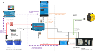
1. Attach the shore power ground in directly to the ground bar in the power distribution, which is the common ground for existing A/C and 12 V system (as it currently is, but run the hot and neutral to the new equipment).
2. Use Lynx negative bus bar as the shared ground reference for all the new equipment.
3. Green wire from Multiplus to lynx represents the chassis ground and is 1/0 or greater
4. Run single 2/0 from Lynx to existing lug across the trailer. (expensive, but lets me have single ground reference and easier than drilling new ground and running all the existing grounds there)
Last edited:
John Frum
Tell me your problems
- Joined
- Nov 30, 2019
- Messages
- 15,233
That will cause cursing and gnashing of teeth.Ok, here's what I'm thinking then:
View attachment 129941
1. Attach the shore power in directly to the ground bar in the power distribution, which is the common ground for existing A/C and 12 V system (as it currently is, but run the hot and neutral to the new equipment.
The ac in hot, neutral and ground should run and terminated together.
Same for the ac outs.
Sounds good.2. Use Lynx negative bus bar as the shared ground reference for all the new equipment.
I think its still a ground loop with the ac ground wire.3. Green wire from Multiplus to lynx represents the chassis ground and is 1/0 or greater
Not following.4. Run single 2/0 from Lynx to existing lug across the trailer. (expensive, but lets me have single ground reference and easier than drilling new ground and running all the existing grounds there)
Is this the same thought as #3?
My eyes are done for the day.
I will look at it later/tomorrow with fresh eyes.
John Frum
Tell me your problems
- Joined
- Nov 30, 2019
- Messages
- 15,233
Ok I've thought about it....
Separate the ac ground from the dc negative busbar in ac/dc distribution panel.
They should be separate from each other and isolated from the frame.
The 12 volt and 24 volt dc_domains are now referenced to the chassis via the lynx busbar.
The multiplus chassis ground lug is connected to the lynx giving a low resistance path for a dc fault inside the chassis.
Also keeps the chassis and ac ground at the same potential.
Also gives an ac hot to chassis fault a path back to the inverter or shore power pedestal.
The idea is the lynx negative busbar is the single point of chassis reference.
I think that covers all the bases.
If anyone else wants to check my logic I would appreciate it.
Last edited:
Ok I've thought about it....
Separate the ac ground from the dc negative busbar in ac/dc distribution panel. - done
They should be separate from each other and isolated from the frame. - Currently both bus bars in the power distribution are connected to the shared ground. Why would I want to disconnect the chassis ground from these bus bars?
The 12 volt and 24 volt dc_domains are not referenced to the chassis via the lynx busbar. - Not sure I understand. The 12V is currently referenced to frame via the shared ground (see image below)
The multiplus chassis ground lug is connected to the lynx giving a low resistance path for a dc fault inside the chassis. - done
Also keeps the chassis and ac ground and the same potential.
Also gives an ac hot to chassis fault a path back to the inverter or shore power pedestal. - Where
The idea is the lynx negative busbar is the single point of chassis reference.
I think that covers all the bases.
If anyone else wants to check my logic I would appreciate it.
I don't think I'm following you, but here's what I think you mean? Not sure how the 12V returns to the battery if the 12V bus bar is isolated from the chassis. Wouldn't I also need to run a 6awg from the existing 12VDC bus bar to the lynx?
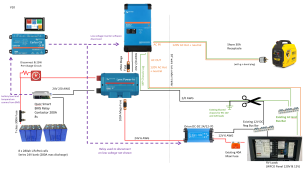
John Frum
Tell me your problems
- Joined
- Nov 30, 2019
- Messages
- 15,233
One question before we get started.
Do the legacy branch circuits have a negative wire or do they all use the chassis for return?
Assuming yes to the previous question.
Your drawing is getting harder and harder to decipher.
The MP2 case grounding lug is attached to the lynx
The lynx is attached to the vehicle chassis as directly as possible with 2/0 awg wire, 2/0 wire is expensive.
The ac out wiring(hot, neutral and ground) to the ac distribution panel is all 10 awg, same as the ac in.
The dc negative between the lynx and the dc distribution busbar in the panel only needs to be 6 awg.
The ac grounding busbar and the dc negative busbar in the legacy panel should be isolated from each other and from the vehicle chassis.
Summary:
The only connection to the vehicle chassis is 2/0 awg directly off of the lynx.
The only connection between the ac and dc domains is the MP2 case grounding lug.
Hope that is clear.
John Frum
Tell me your problems
- Joined
- Nov 30, 2019
- Messages
- 15,233
In the combo distribution panel are the dc negative and ac ground busbars isolated from the chassis?
Is it easy to isolate the from each other?
Just for fun I did my own version of your topology using drawio.
 tinyurl.com
Is it easy to isolate the from each other?
Just for fun I did my own version of your topology using drawio.
Flowchart Maker & Online Diagram Software
The legacy DC 12V system has return wires on all circuits which go to a common 12VDC Neg Bus Bar with one exception: The legacy battery negative terminal is grounded directly to the chassis and uses the chassis to return from the 12VDC Neg Bus Bar. (As shown in that image with the floor plan).One question before we get started.
Do the legacy branch circuits have a negative wire or do they all use the chassis for return?
Thanks for sticking with me. I think I understand what you're saying now:
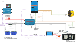
This all makes sense! Does the drawing look accurate now?The MP2 case grounding lug is attached to the lynx
The lynx is attached to the vehicle chassis as directly as possible with 2/0 awg wire, 2/0 wire is expensive.
The ac out wiring(hot, neutral and ground) to the ac distribution panel is all 10 awg, same as the ac in.
The dc negative between the lynx and the dc distribution busbar in the panel only needs to be 6 awg.
The ac grounding busbar and the dc negative busbar in the legacy panel should be isolated from each other and from the vehicle chassis.
Summary:
The only connection to the vehicle chassis is 2/0 awg directly off of the lynx.
The only connection between the ac and dc domains is the MP2 case grounding lug.
Hope that is clear.
This is great, because I already have all the correct size wires running under the trailer for this setup. Will get some build photos up soon, once the 2/0 wire comes in.
Similar threads
- Replies
- 16
- Views
- 490
- Replies
- 10
- Views
- 873
- Replies
- 4
- Views
- 345


