diy solar

diy solar

Detailed look at cell imbalances using monitoring software for Jakiper / SOK 48v server rack

Lardino

New Member
Joined
Mar 22, 2022
Messages
82
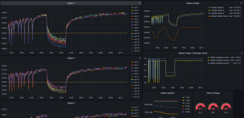
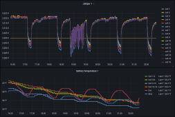
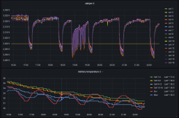
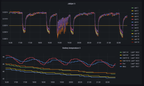
I have three Jakiper JK48V100 48v server rack batteries. The cells differential goes far apart on charging. The video I made show how I interpret the data from the past 24 hours to see what is happening the all 16 cells in each battery pack. I am looking for feedback on my analysis and also on any charging remedies short of opening up the battery pack and charging each cell individually.
Since the Pace brand BMS ( also used in SOK batteries) can only handle a small current to balance the cells , I am thinking I will need to set a very low current half an amp or so and leave the battery to charge and hopefully balance over the course of days . The bms only balances the cells when certain criteria is met. The stock settings that the battery came with was to balance cells only above 3.5v and more than 20 ma differential between cells. Jakiper tech remote connected to my batteries and reset this to 3.3v and 20 mv differential after I initially discussed the problem with them. The balancing may have gotten a little better with the changes but is still way off.
I explain in the video why I think this is the case.
I welcome any discussion about this .
If anyone is interested in trying out the software I used it is available free with install instructions at following link. It should work for SOK server rack batteries too but no one has confirmed that to me yet. Since it Pylontech protocol it may also work with other brand bms that use that and have a console port.
Thanks
 
Does the BMS have a setting that allows the balance to continue after the charge stops? If so, set it so that the balancing is not dependent on charging. You will probably find that the batteries will balance out within a few days. All the BMSs that have sub-1A balance current will fail to keep things in balance if they only balance during charge. You mention that the BMS is the same as in SOK. I do not know about the SOK server-rack batteries, but their 'drop in' 12V batteries only Ballance during charge. SOK support has said they will fix this, but the fix won't be available for existing batteries.

As far as the voltage spread during float, I suspect the float voltage is a bit high and the cells are still charging.
I don't think it has a setting for balancing after charge stops. When I first got the batteries I watched the Jakiper provided software closely. It has an indicator of when each cell is balancing ( we haven't been able to find a report for that for software I use). So yes the balancing only worked when it was charging. And that was frustrating because when I first got batteries about time they charged, voltage soared so high charging stopped.
I will look at the bms settings again to see if that is an option. Jakiper locks out changing bms settings but they have been receptive in the past to changing them remotely.
I wonder why semi sophisticated bms like these wont do that ? I was thinking it might be because they were designed on the assumption that the cells would be more in balance from the start and then just sit in a server environment where they aren't cycled much .
Thanks for your suggestions
 
BMS's do not regulate current other than stopping over/under charging by disconnecting BMS. Balancing current on those packs is likely insignificant to cause a shift in cell voltage (other than >3.4v cell voltage actual balancing)

BMS communications back to inverter/charger can reduce overall charging current when any pack's BMS reports a cell getting close to over voltage.

Besides terminal connections and wiring resistance, there can be some temperature variations between the battery packs based on their position in rack.

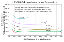
Keeping temperature between battery packs similar is very important. Battery impedance goes up significantly as cells get cold. Cell impedance rises at a greater rate below 15 degs C.

This has two positive feedback problems making a bad situation worse. First is the warmest pack supplies more of the load current. Second is the battery supplying more of load current may have a warmer BMS heating due to BMS losses at the greater current, which contributes to heating that battery enclosure up even more, causing that pack to supply even a greater percentage of load current.

No load open circuit LFP cell voltage is not affected by temperature very much. It is not until there is load current where the cell impedance causes a voltage slump in cell terminal voltage.

You should add pack temp tracking to your data collecting.
 
Last edited:
BMS's do not regulate current other than stopping over/under charging by disconnecting BMS. Balancing current on those packs is likely insignificant to cause a shift in cell voltage (other than >3.4v cell voltage actual balancing)

BMS communications back to inverter/charger can reduce overall charging current when any pack's BMS reports a cell getting close to over voltage.

Besides terminal connections and wiring resistance, there can be some temperature variations between the battery packs based on their position in rack.

Keeping temperature between battery packs similar is very important. Battery impedance goes up significantly as cells get cold. Cell impedance rises at a greater rate below 15 degs C.

This has two positive feedback problems making a bad situation worse. First is the warmest pack supplies more of the load current. Second is the battery supplying more of load current may have a warmer BMS heating due to BMS losses at the greater current, which contributes to heating that battery enclosure up even more, causing that pack to supply even a greater percentage of load current.

No load open circuit LFP cell voltage is not affected by temperature very much. It is not until there is load current where the cell impedance causes a voltage slump in cell terminal voltage.

You should add pack temp tracking to your data collecting.
Good idea on the battery pack temps - I am able to get all 6 temp sensors data . I only have the lowest pack set up for that now though since it is probably the coldest. I didn't realize that a colder lithium battery would change that much compared to the others. But what you say makes sense since battery 3 is much different than the others and it is the bottom one.
I goofed up this fall - cold weather snuck up faster than I was ready for , so my hastily built insulation around the batteries is not the best . I have a space heater in there set on low and temperature control it with a probe lower to the bottom battery. I was assuming that everything above freezing would be the same. There is a lot to learn about lithiums.
I can make that battery temp graph now and look backwards in time to see how it corresponds.
What I mean by the current regulation is that I have watched the current go down to a lower current , and then to a negative current when the bms is trying to maintain the voltage to the other batteries. I saw that happening when I first got the batteries , all the batteries were warm, and there was not much load on the packs.
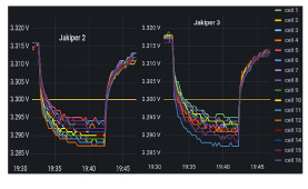
Below is screenshot of battery 1 top , and battery 3 bottom. On the right you can see how the discharge current is much less for the battery 3 ( colder one I think ) during load than the other two batteries . I am making graph to compare the temperatures .
Thanks for the info . 1672021057544.png
 
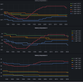
Temperature comparisons from last post - yes there is > 10 degree F difference between top and bottom batteries.
1672021670598.png
 
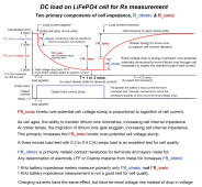
On the graph with 10 minute spread visible you can see the overpotential voltage exponential decay. It normally settles out (or recovers) in about 3 minutes at 25 degs C, but slows down as temp gets colder. Low temp or aging increases total decay amount of R_ionic. This is why keeping temps between cells consistent is important.

The abrupt, near vertical immediate voltage drop is R_ohmic of cells plus and interconnect resistance between cells x cell current. The voltage sampling rate by the BMS makes an accurate reading of R_ohmic a bit difficult because the R_ohmic voltage drop slope is almost instantaneous.

Maybe a suggestion would be to keep your color codes consistent to cell position number.

Battery Impedance.png

Rs vs Temp and SOC for LiFePO4 cell.png
 
Last edited:

RCinFLA

There is a lot to consider and so much for me to learn .
Not sure if you meant I should keep the color codes consistent between temps and voltages ? I figured out how to put labels on cell temps . Four temp sensors are between cells , one is for mosfet ( I think) and the other one I believe is more of the air temperature inside the battery case. All the colors for temp locations should be the same on all batteries.
I never realized the temperature had that much effect on the batteries because most all we ever hear about is just to keep them above freezing for charging and that is all I had considered. If it warms up a bit here in Wisconsin I may be able to redesign my battery heater option to try and make it more consistent than it is now.
Thanks again for the detailed info .
1672028696312.png
1672028754874.png1672028796839.png
 
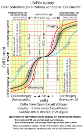
The overpotential slump is a good indication of cell condition, with consideration that it also drops more at cold temperatures and amount of load current. Over the useful lifetime of cell, the overpotential slump voltage will increase by 2x to 3x of its new cell value. You want this aging to remain matched which is why you want to keep cells in balanced SoC over the use life. If cells are continually run out of balance, not only do you get less net capacity out of battery pack, but also wear the cells at different rates, increasing their mismatching.

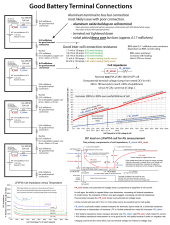
Other issues to contend with is BMS calibrations and variable amount of cell interconnection resistances, usually due to their connection resistance to cell terminals. These rack battery packs cell interconnects are often spot welded on cells so you cannot do much about it if there is variance.

If cells are well matched, interconnections are same resistance, and BMS calibration is accurate, all the cells exponential slump should match and the graphs should be on top of each other.

It is not clear what the battery current is for your graphs. On the other graph it shows about 4.5A and 5A. This is low current to have this much slump voltage. For good resolution you should test with 0.2 to 0.4 C(A) of discharge current. Assuming these are 100 AH cells this would be 20 to 40 amps of discharge current. At low current it is normal to have some cell overpotential voltage variance which is why you need enough load current to get well above this variance.

The variables effecting slump curve are, actual battery impedance, current through cells, temperature, cell interconnect resistance and BMS calibration accuracy. On battery impedance, R_ohmic is like a fixed resistance but R_ionic increases with cell current. Cell impedance is fairly flat from about 20% to 90% state of charge.

You can check accuracy of BMS and cell interconnections with a DVM on cell terminals directly. Probes of DVM need to be on cell terminals directly, not on top of bus bars. Make the DVM measurement after exponential slope reaches equilibrium in about 3 minutes after load current applied. Obviously, you have to open up unit to do this and should have a DVM you have confidence in its accuracy.

Imbalance in load current sharing between parallel battery arrays is somewhat self-compensating. Battery array taking more current will have greater voltage slump which should shift more current to lesser drawing battery arrays. A BMS drawing greater current will have warmer MOSFET's temperature which increases MOSFET series resistance, again shifting more current to lesser drawing battery arrays.

Too much cold temp variance between battery packs can be a significant issue to current sharing balance.
Batt Comparison.pngGood battery connecitons.png

LFP Over-potential Chart.png
 
Last edited:

RCinFLA

Thanks again for the info. I read and understand most of what you showed above. I think I will redo my battery interconnects mainly so I can remove one battery at a time if I want to try to individually balance the cells ( need to open it up).
Besides the all the poor climate control that I have , what would be the best process for me to balance one battery at a time ? Should I try to top balance each cell ? And if I was to get them all done - can I then return a 100% SOC battery with the other battery packs that may be lower ?
The things you have posted above certainly would explain why some people report great performance from their lithium batteries , while others have not so good results or longevity.
Most people don't do the detailed monitoring or pay too close attention to these batteries cells. Many , including myself, going into this lithium battery upgrade , is looking for fantastic lithium plug and play power performance. I heard someone comment in past that if we had done more sophisticated individual cell monitoring and balancing on lead acid batteries , they could have really lasted a lot longer than many did. Those lead acid take some abuse compared to lithium.
 
First thing would be to check the BMS reporting numbers for calibration accuracy.

You can put the 'hottest' battery at the farthest connection point to have a little more cabling resistance to balance load current distribution, but you need to control their temp matching first.

You should ensure the cells are balanced in SoC on each battery array. It requires a full charge to 16x 3.55v = 56.8vdc absorb and held there for an hour or two or until all cells reach same voltage. BMS only balance dumps a cell when it gets greater than 3.40 vdc and dump current is likely only about 100-150 mA's.

If cells get too far out of balance (about 1% difference in SoC) you will start to have BMS cell overvoltage shutdown of charging due to highest SoC cell reaching the maximum cell voltage when you try to do a full absorb balancing charge.

Many folks have this problem with self-contained 12v LFP batteries with no individual cell monitoring and user not fully charging them for a long period of time preventing any balancing from happening. They either complain of loss of capacity or battery going open circuit when they finally attempt to do a full charge. It can take a long time to get them back in balance if you let them go too long of time without fully recharging to allow balancing (several days at absorb charge voltage to get balanced again)

1% SoC imbalance on 100 AH cells with 100 mA balancing bleed will take about 10 hours at absorb charge voltage to rebalance.
I can compare the BMS SOC reports to my Midnite Classic Controller Whizbang shunt ( for all packs in common) . When I first put these all online in warmer temps , the Midnite SOC and bms SOC tracked very closely to each other. But when it got colder and I started drawing the batteries down more , the Midnite and bms SOC were getting farther apart. I started to trust the bms SOC but had batteries shut down when they said 50 to 60 % . The Midnite had been more correct all along. After the batteries shut down and I restarted them and bms reset too I think , then the bms SOC and Midnite were on the same page again.
It is good to have more than one source of monitoring !
I had exactly what you say with BMS overvoltage shutdown when I first got the batteries. It is unfortunate that Orient Power /Jakiper don't write up a detailed manual like you and other described on how to bring their batteries into balance. They do provide software that shows the balances. But in reality they shouldn't be shipping such imbalanced batteries in the first place. So many of us want to believe that the bms in them will do the magic balancing by themselves - but of course I am finding out that isnt the case. But learning by mistakes and example is a good thing if you can pay the price.
My only hitch now is how to balance three different batteries that I have in use now. I do have a 24v lead acid system I can put back into primary service though.
So much to learn - I appreciate your help and will update as I try to get these in balance. I may have to set up another independent monitor for the batteries I am balancing if I want the same history as I get now.
 
Jakiper/ Orient Power techs suggested I use 1.5 amp charge from power supply to balance.
Balancing current is 40-75mA
 
Jakiper/ Orient Power techs suggested I use 1.5 amp charge from power supply to balance.
Balancing current is 40-75mA
With that suggestion, they are admitting to a major flaw in the product. You should not have to do that!!! If they designed the balance algorithm correctly, that would not be needed even with a very low balance current. All they have to do is start the balance as soon as any cell is above 3.4V and not put restrictions like 'it must be charging' on it. Let it balance during float. Even with a small balance current, this will keep all but the worst cells balanced. I fear that some people putting these products together do not understand some of the important aspects of LiFePO4.
 
The greater the balancing current relative to charge current, the better the chance to win the race between achieving balance before the highest SoC cell hits overvoltage limit of BMS.

Balancing only above 3.4v, where a cell is close to full charge will increase the ability to sense which cells need balancing because cell voltage rises quickly above 3.4v during charging.

Balancing current alone, will create some overpotential voltage slump (or bump up if active balancer) which can cause BMS to make some wrong calls on which cells need balancing. On the above reply overpotential graph, notice the 10-20 mV overpotential created for very low cell current.

Having some charging current, which is applied equally to all series connected cells, will establish a dominate overpotential bump on all cells so the individual cell balancing current will create insignificant additional bump or slump in net overpotential.

Balancing above 3.4v also pretty much says you will only balance during charging since it takes some charging current to get a cell above 3.45v.

During charging, after a cell gets above 3.45v and approaches full charge, overpotential is slowly traded for surface charge build up, as charge current tapers off, which is just a capacitance voltage charge build up on the cell electrode layers, mostly in the graphite negative electrode. This surface charge has insignificant capacity, amounting to about 0.01% of real cell capacity.

This surface charge will bleed itself off in a few hours to a few days and cell will eventually drop to less than 3.5v if cell is left unloaded. Many folks doing a top balance to 3.65v see their cells bleed this surface charge off at different rates and incorrectly think their cells are not balanced well. A LFP cell with a rested open circuit voltage above 3.45v is fully charged.

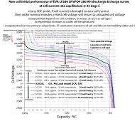
On the graph below, notice how the cell voltage reacts as cell approaches full charge for the various listed charging currents. The greater the charging bulk current rate, the sooner the voltage will start to rise as it approaches full charge and the less actual SoC will be as voltage starts to rise. This means higher charging rates will have a longer absorb time required until charge current tapers off where cell truly reaches full charge.

If you charge at high current, there will be greater cell overpotential voltage bump up to support the greater cell current, and if you terminate charge when it just hits absorb voltage the cell will not be fully charged. You have to wait for cell current to taper down which takes longer at high charging currents.

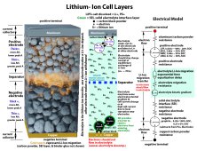
When a cell approaches full charge, it is like a game of musical chairs. Li-ions entering graphite negative electrode have a harder time finding an empty parking spot. This requires greater overpotential driving force to push li-ions which is why the cell voltage rises quickly as cell approaches full charge.

Extra trivia, the slight cell voltage bumps in the discharge curves are caused by the way the negative graphite electrode layer lattice manages its multi-layer 'parking garage' to lithium-ion storage. The two most dominate bumps show up around 55% and 5-10% SoC.

LF280 AH battery dischg 0.1C-1.0C.png
 
Last edited:
With that suggestion, they are admitting to a major flaw in the product. You should not have to do that!!! If they designed the balance algorithm correctly, that would not be needed even with a very low balance current. All they have to do is start the balance as soon as any cell is above 3.4V and not put restrictions like 'it must be charging' on it. Let it balance during float. Even with a small balance current, this will keep all but the worst cells balanced. I fear that some people putting these products together do not understand some of the important aspects of LiFePO4.
To be fair - I specifically asked what would be the best current if I want to try and balance my batteries using a controlled cc cv that can be provided by a regulated power supply.
I will have to look through all the settings for what the bms can and can't do. As far as I know this is the same BMS that SOK uses in their server rack batteries - though perhaps there are different models of bms , a new one may have different features, and settings. It is difficult to know all the variables involved. From what I have seen there certainly is an evolution happening with bms design and capabilities as there should be. Just like happens with charge controllers, inverters, and everything else. We jump in at the time we do and the price point that we are comfortable with.
 

RCinFLA

There certainly is a lot of chemistry and physics to consider . I will have to study what you just presented so I can absorb all the details.
Perhaps I can in the future use the monitoring to see exactly what is happening with the cells .
Do you have any video presentations on lihiums posted anywhere ?
Thanks
 
There are many videos on Youtube. A lot are very basic, some have greater tech details.

This may help understanding a bit.
Li-Ion Graphite battery model.jpg
 
I've just joined to say I've similar issues and am pretty disappointed by the naff balancing.
I've been trying to get my cells balanced the last few days by doing the last bit of charge with a 1.2A current from an external supply.
Watching in PbmsTools I can see my highest cell hit BL mode, but it drops such a tiny current that even with a feeble charge current it still climbs towards protect (3.65) whilst I've another cell still trying to bulk charge.
~
My battery is a completely unbranded 100Ah, which I eventually figured out uses the PACE BMS.
Is the Admin password for PBMS known at all, so I can try dropping the balance voltage?
Which version of the program are you using ?
What is the balancing setpoint at now ? And also what is the balance differential set for ?
I have seen people say generic passwords - I need to try and remember what they were or where I saw them.
I think it was either in the comments on some of my posts here on this forum or else on some of my youtube video comments.
someone suggested this in past pace123
There may be others that were suggested.
Let me know if it works !
I haven't tried any of them though.
 
Back
Top