diy solar

diy solar

DEYE Inverter UL Listed available in US

Also bear in mind the heat. These will heat up fast when there is 8KW+ of PV, 6KW+ of loads and charging the battery through the DC-DC at a few KW. So if you're in a hot environment, I would manually limit the PV input to 8KW-10KW, depending on what is appropriate for the loads vs environment. The battery will charge slower if the inverter is under a full load but it will keep the unit from derating due to overheating.
? tropical climate so temperature controlled room for inverters and batteries.
 
Thats kind of my feeling as well, although my panels would potentially be 480vdc@ 13a on each mppt(10 panels)! I know i wont see this constantly so it was a comfortable range for me.
The rated voltage of the panel is at 25C if the ambient temperature of the solar panels is much lower this voltage will be higher, check the specs of your solar panel for Voltage Temperature Coefficient before you get a surprise on a cold day.
 
The rated voltage of the panel is at 25C if the ambient temperature of the solar panels is much lower this voltage will be higher, check the specs of your solar panel for Voltage Temperature Coefficient before you get a surprise on a cold day.
Yeah i dont realy have to worry about that here in the bahamas it's almost always hot, we call 25c cold here lol...well i hope to never have that issue
 
PM me if you want the SMA protocol. CAN bus only.
Hi,
I'm a solar installer in the UK, recently became aware of the SunSynk 8kW hybrid inverter, which looks like it will be the perfect fit for an upcoming installation. I usually build composite battery using REC BMS controlling Victron inverter/charger.
Are you able to confirm whether the REC BMS is compatible with the SunSynk CAN BUS protocol and will fully control the inverter?
many thanks
Edd
 
(This is a cross-post from another thread, just wanted to mention it here also).

Deye is now canceling the distribution and manufacture of the split-phase model in favor of SOL-ARK distribution only for all of North America. Not even Chinese suppliers can purchase split-phase models anymore. I've confirmed this in several different ways.

We have some inverters in the queue currently being manufactured at Deye and I have access to stock but as soon as it's out, there will be no more available.
 
Hi,
I'm a solar installer in the UK, recently became aware of the SunSynk 8kW hybrid inverter, which looks like it will be the perfect fit for an upcoming installation. I usually build composite battery using REC BMS controlling Victron inverter/charger.
Are you able to confirm whether the REC BMS is compatible with the SunSynk CAN BUS protocol and will fully control the inverter?
many thanks
Edd
I'll PM you!
 
Off-topic but Deye is rolling out a 3KW 24V hybrid now based on the current platform. Kinda tempting for smaller applications. I might would even attempt a mobile application. Does require the use of an autotransformer but for super value for the price. A little less than Victron I would say when it comes to a total installed cost for the same wattage. Stackable up to 16 inverters in parallel.

View attachment 59386
Does this new SUN-3K-SG04LP1 include a CT sensor and support zero-export-to-CT?
 
Yes. It's basically just a very small SOL-ARK/Deye. Built on the same platform.
Cool.

But if you use an Autotransformer to drive split-phase output, where do you connect that single CT sensor to limit export on either leg?

Also, the model you linked to is 230V but does Deye (or one of their OEM partners) offer a similar CT-enabled single-phase model supporting 120V single-phase output?

If so, 2 units could be connected out-of-phase, each with it’s CT sensor on it’s respective leg to limit export to zero…
When you are using a 120/240V grid input using these single-phase 230V inverters, there is a couple of ways to handle it. One method is to bring 240V (L1+L2) through the inverter and leave the grid neutral unconnected. A single CT on either line will be fine since is a single circuit through a single center-tapped winding on the pole but you're not returning current through the center tap. You would use an autotransformer to create a new center tap and create 2x brand new 120V legs on the load side of the inverter.

There is more to it than this so careful planning/engineering is required but that's one example.
So you are saying that an Autotransformer will automatically rebalance the load so that consumption from grid will always be balanced (equal on both legs)?

So without any inverter present, if you just connect an (appropriately/sized) Autotransformer to L1 and L2 the current drawn from the grid will be 50% through L1 and 50% through L2 even though 100% of the load is on only one leg?

If that is true, then I understand how connecting a 240V single-phase inverter with CT sensor on either leg-to-grid would deliver zero export (without even needing to directly connect the inverter output to the Autotransformer, right?).

The only way one leg could be driven to zero export is if the other leg is exporting zero as well (sounds almost too good to be true ;)).
 
So without any inverter present, if you just connect an (appropriately/sized) Autotransformer to L1 and L2 the current drawn from the grid will be 50% through L1 and 50% through L2 even though 100% of the load is on only one leg?
Yes, up to the maximum transfer capacity of the autotransformer.

If that is true, then I understand how connecting a 240V single-phase inverter with CT sensor on either leg-to-grid would deliver zero export (without even needing to directly connect the inverter output to the Autotransformer, right?).
Yes, assuming an appropriately sized autotransformer or set of autotransformers. I would also set the grid positive value in the inverter very high. Possibly as high as 200W or more to ensure a positive input from the grid.

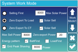
Note the item marked zero export power:

1636345484513.png

NOTE:

I would also make sure that the autotransformer(s) are installed AFTER the inverter on the load side. If they are installed between the grid and the inverter, you'll lose power to all 120V loads when the grid goes down because the inverter will go into anti-islanding mode and there will be no neutral return back through the transformers. This is not only inconvenient, but it can also be very hazardous. You never want to lose the neutral without killing the inverter load output completely.
 
Yes, up to the maximum transfer capacity of the autotransformer.
Cool. So as an example, the 2 1kW GTIL inverters I have currently will often be maxed out at 1000W on one leg while the other leg is underutilized at <100W.

I was planning to track down the loads responsible and do some leg-swapping on the mains panel to attempt to get better typical load balance (which is a PITA), but this is making it sound as though if I simply added a 1kW Autotransformer to my system, I’d get better balance between the 2 GTILs so that they both drive much more equal output levels at all time, is that correct?
Yes, assuming an appropriately sized autotransformer or set of autotransformers.
So, for example, if I wanted to use a 3kW zero-export single-phase inverter like this one, I would want to add an Autotransformer of at least 3kW, right? Are there any Autotransformers of this size you have experience with and could recommend?
I would also set the grid positive value in the inverter very high. Possibly as high as 200W or more to ensure a positive input from the grid.

Note the item marked zero export power:

View attachment 71681
That’s a nice interface - did you ever indicate approximate pricing for the 24V 3kW model?

And yes, zero is not necessary - anything under 10% of my average of 600W would be fine (though 200W is higher than I’d hope for).
NOTE:

I would also make sure that the autotransformer(s) are installed AFTER the inverter on the load side.
This I’m not understanding. I’m connected in parallel, so grid into mains load panel and inverter into mains load panel with all loads connected to both in parallel through the breakers. So my inverter is not in between the grid and the load such as is the case for a classical hybrid inverter.
If they are installed between the grid and the inverter, you'll lose power to all 120V loads when the grid goes down because the inverter will go into anti-islanding mode and there will be no neutral return back through the transformers. This is not only inconvenient, but it can also be very hazardous. You never want to lose the neutral without killing the inverter load output completely.
Oh, now I understand - you are talking about backup capability through the critical loads output - backup is not a feature that matters to me.

If I did connect the Autotransformer at the Critical Loads output (even though I have no load there), wouldn’t that mean the full load imbalance has to glow through the inverter?

I suppose the inverter can handle that load and with the Autotransformer located on the Critical Loads output, I’d always have the option of adding some critical loads to a new panel in the future…
 
where do you connect that single CT sensor to limit export on either leg?
If it is a 240 volt inverter is there a reason you could not use CTs between the meter and the bus, As far as I know the utilities only measure export at that point, I do not know if they care about unbalanced loads.
 
If it is a 240 volt inverter is there a reason you could not use CTs between the meter and the bus, As far as I know the utilities only measure export at that point, I do not know if they care about unbalanced loads.
Some have done that and apparently gotten away with it, but the smart meters are certainly able to detect unbalanced export on only one leg and I don’t want to take the risk of getting flagged.

I have a grandfathered NEM agreement I don’t want to violate.
 
the smart meters are certainly able to detect unbalanced export on only one leg and I don’t want to take the risk of getting flagged.
How would they be able to detect differences if the meter only measures 240 volts? My assumption is based the fact that there is no neutral at the meter. You should be able to test my assumption at any typical smart meter.
 
Last edited:
Some have done that and apparently gotten away with it, but the smart meters are certainly able to detect unbalanced export on only one leg and I don’t want to take the risk of getting flagged.

I have a grandfathered NEM agreement I don’t want to violate.
Most meters installed on residential splitphase homes have only one ct in them. Both mains wires/legs go thru this one Ct in opposite direction of each other. This is why the 240v GTIL2 output can be used on a splitphase power supply from electric company and there’s no backfeed detected. and it works very well
 
How would they be able to detect differences if the meter only measures 240 volts? My assumption is based the fact that there is no neutral at the meter. You should be able to test my assumption at any typical smart meter.
My meter has 3 wires into it, L1, L2, and ground/neutral from the pole.

The meter only sends L1 and L2 on to get main breaker, where a new neutral is bonded to house ground, but the meter can easily detect one leg expiring while the second leg is consuming by comparing to pole neutral/ground.

And even if the meter only measures/reads kWh based on 240V, that doesn’t mean it can’t also recognize a fault situation based on L1 vs L2 consumption to set/issue a flag.
 
Most meters installed on residential splitphase homes have only one ct in them. Both mains wires/legs go thru this one Ct in opposite direction of each other.
Is there any place to check smart meter design based on model (or electric utility). If my smart meter only uses a single CT sensor, that would simplify things a great deal, but I have enough riding on it that I’d want to be certain..,
This is why the 240v GTIL2 output can be used on a splitphase power supply from electric company and there’s no backfeed detected. and it works very well
Making a 240V GTIL2 offset splitphase 110 & 240V consumption is not the question - I know that can be done and that the meter will properly read 0kW consumed even if L1 is exporting an equal current to what L2 is consuming.

And I understand that if the smart meter only see see through a single CT sensor, that there is no way it can detect (or flag) that imbalance.

But I’ve read about GTIL customers operating at 240V to offset split-phase consumption having the export imbalance be flagged by the meter so that the utility came out to inspect and nabbed them.

Which is why I’m interested in any means to validate the precise sensing capability of my smart meter…

As I stated earlier, my smart meter receives ground/neutral from the pole/grid along with L1 and L2…
 
Back
Top