I am glad my documents helped you understand. My objective in the documents is to help people understand the physics behind things so they can better deal with the real world situations. Sadly, the NEC allows that extra ground rod (But does not require it). There are a lot of sources both in the solar industry and on the internet that put out bad information about grounding. Last I heard Mike Holt was still trying to get the NEC to publish an emergency warning about this but he is fighting the momentom of a large population of people that don't fully understand.
It really helped!, some documentation like NEC goes to technical and abstract, very hard to go around... your manuals are are distillation of a bunch of reading, and even with pretty diagrams!, much easier to read and get the basics behind our systems.
Seems like Mike Holt has spend his whole life fighting against the common knowledge and NEC
")
..
That sounds like a good connection to earth. If possible, that should be the only connection to earth.
Got it, new installers also wanted to put a new independent ground rod, with all this i can fight them about it.
Yes..... that is a ground loop. Unfortunately in situations like yours it can be difficult to meet code and avoid ground loops.
The NEC is difficult to sort out in situations like this and I am certainly not a NEC expert, but I don't see a provision that allows the metal building roof to be the ground path. Even if there is a clause someplace that allows it, I could easily believe inspectors would not.
The best you can do is to make sure the ground cable connects to the rest of the grounding system as close to the earth connection as possible.
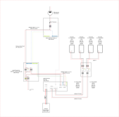
Ok, suppose you don't care too much about what NEC wants, and you give more weight about what its technically right. What could be the best setup scenario?, don't attach a ground to PV at all?, just measure with a "groundometer" to see if you have a good connection between PV aluminum structure and your ground end? (Should be, as there is like 5000 screws connecting the roof to the beams, and all structure connections are soldered).
Failed to mention that im outside US, but our code its a copy of NEC and we use the same bi-phase 220V setup. Our inspectors dont even go inside the building, so in theory i can do whatever i want from the door. (At leas in an small installation like this, a bigger system would receive a good check).
Warning: PURE SPECULATION FOLLOWS:
Based on the documentation I am guessing that their design center is a stationary set-up where the AC-in always has a N-G bond and that bond is carried forward to the output. If that is the case then nothing more is needed for a stationary system.
However, if it is a mobile set-up, then a lot of times you won't be plugged into shore power and therefor there is no N-G bond on the AC-in. In that case, the relay mentioned in the documentation is needed to re-establish the bond. (Since mobile set-ups are outside their target market, they did not spend the extra couple bucks to build the relay in.
It is criminal how poor some of the inverter documentation is around the critical function.
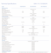
With the lack of documentation i could only be sure if i do some testing (Not sure how difficult it would be) or asking other owners, unfortunately Deyes are not common in USA. In my experience the manufacturer / seller doesn't help too much with this kind of questions (As you experience with Growatt). indeed very poor documentation, but that's the cost you ptake for an inverter 1/3 of the price.
So im left with testing and checking better documentation, i can see that sol-ark has some differences, but i expect that most of the fundamentals are carried over. I take them only as a reference, as even between versions of Sol-ark there is some differences in the documentation, like the last model, that added a bigger passtrough (60A) and NEMA enclosure.
I think the differences between DEYE and Solark would be mainly the firmware and bottom connections... i plan on uploading some photos of the internals so we can start to get a better understanding of it
.
-------------------------------------------------------
Againt thanks for all the info!