


SomebodyInGNV
New Member
- Joined
- Jun 3, 2020
- Messages
- 182
Please save me from myself.
I've collected the parts for my solar system and will start building it this week. (I'm waiting for delivery of the batteries.)
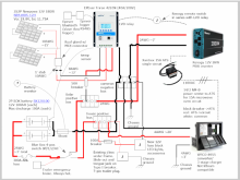
My plan is below. I hope it's readable. I used a trial version of SmartDraw and have only 4 more days to use it. I can't generate a readable PDF because it's covered with watermarks.
This is the system I referred to in message 170644, here: PV array breaker/switch size? 720W of panels will lay flat on the roof and will be subject to shading. Wiring on the roof will be the 10AWG and MC4 connectors provided with the panels. I may need about 10' of extension. I'll get something ready-made with MC4 connectors, because the roof gland has them, as well. From inside the roof to the SCC (about 10') I'll use 8AWG. They'll be paralleled with an MC4 branch connector.
6AWG welding cable will be used from the SCC to the positive bus bar. It's the largest allowed in the terminal. From the battery to bus and to the inverter will be 2AWG. The inverter will draw < 200A at the rated current and 370A for a brief surge. The wire size calculator says 2AWG is acceptable for 2% drop over 6 feet (round trip) and 370A will result in a 5% drop. Being very short term, is that okay?
I'm using the OEM WFCO 3-stage lead-acid charger and will rely on the solar system to charge the LFP batteries completely. I'm replacing the ~20' of OEM 8AWG conductor from the converter/charger to the battery with 4AWG. I will replace the single conductor/chassis ground with both positive and negative conductors. The chassis grounds will be improved with 4AWG, as well. That and some new and existing 12V loads will be on a separate positive bus, allowing disconnecting the trailer from the battery while leaving the solar system engaged. The Blue Sea switch I have allows the converse, as well.
A Xantrex 15A ATS will be plugged into the inverter. I'll run 14/3 NM-B from the power center. One leg will be from the 15A breaker for the microwave oven circuit. I'll connect the return leg to the wire I pulled out of the breaker to make way for the 14/3.
I'm wiring the Renogy remote switch in series with the relay com slave module on the SCC. That way either the switch or the relay will cut off the inverter. The remote switch and the battery monitor will be in one place on the kitchen wall next to the remote display of my Progressive Industries EMS.
All suggestions are appreciated.
Edit: tweaked image and added color. No material changes made.

I've collected the parts for my solar system and will start building it this week. (I'm waiting for delivery of the batteries.)
- Newpowa 180W 12V monocrystalline panels (Datasheet) in 2S2P array
- EPEver Triron 4210N MPPT SCC (Manual)
- SOK Battery 12V 100A LFP battery (Spec sheet) in 2P array
- Renogy 2000W 12V PSW inverter (Datasheet)
- Xantrex 15A inline transfer switch (Owner guide)
- WFCO WF-8955 converter/charger (Manual)
- Plus cables, bus bars, fuses, switches and breakers as appropriate.
This is the system I referred to in message 170644, here: PV array breaker/switch size? 720W of panels will lay flat on the roof and will be subject to shading. Wiring on the roof will be the 10AWG and MC4 connectors provided with the panels. I may need about 10' of extension. I'll get something ready-made with MC4 connectors, because the roof gland has them, as well. From inside the roof to the SCC (about 10') I'll use 8AWG. They'll be paralleled with an MC4 branch connector.
6AWG welding cable will be used from the SCC to the positive bus bar. It's the largest allowed in the terminal. From the battery to bus and to the inverter will be 2AWG. The inverter will draw < 200A at the rated current and 370A for a brief surge. The wire size calculator says 2AWG is acceptable for 2% drop over 6 feet (round trip) and 370A will result in a 5% drop. Being very short term, is that okay?
I'm using the OEM WFCO 3-stage lead-acid charger and will rely on the solar system to charge the LFP batteries completely. I'm replacing the ~20' of OEM 8AWG conductor from the converter/charger to the battery with 4AWG. I will replace the single conductor/chassis ground with both positive and negative conductors. The chassis grounds will be improved with 4AWG, as well. That and some new and existing 12V loads will be on a separate positive bus, allowing disconnecting the trailer from the battery while leaving the solar system engaged. The Blue Sea switch I have allows the converse, as well.
A Xantrex 15A ATS will be plugged into the inverter. I'll run 14/3 NM-B from the power center. One leg will be from the 15A breaker for the microwave oven circuit. I'll connect the return leg to the wire I pulled out of the breaker to make way for the 14/3.
I'm wiring the Renogy remote switch in series with the relay com slave module on the SCC. That way either the switch or the relay will cut off the inverter. The remote switch and the battery monitor will be in one place on the kitchen wall next to the remote display of my Progressive Industries EMS.
All suggestions are appreciated.
Edit: tweaked image and added color. No material changes made.
Attachments
Last edited:
")