diy solar

diy solar

Did I mess up?

severin20

New Member
Joined
Jun 18, 2020
Messages
28
Hello,

My name is Severin and this is my first ever solar install.

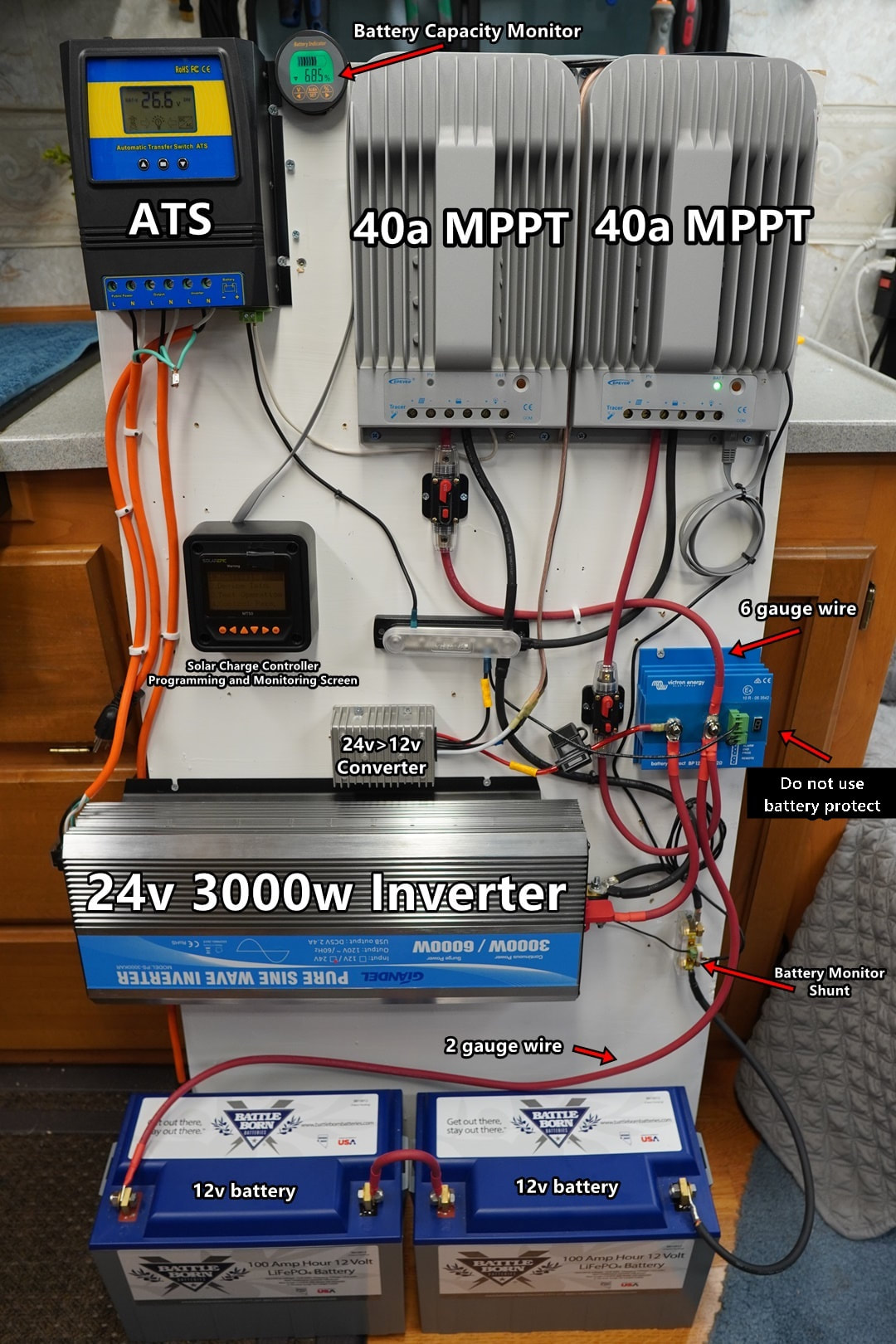
I purchased everything recommended for the 24V 4000 watt system as shown here.

My question is how do I connect 4000watts to the 40amp charge controllers that I have 2 of.

I got 16 panels at 250watts each. Hoping to wire 8 of them into one charge controller and 8 of them into the other controller.

The panels are 24v with the following specs:

  • Rated Power: 250W
  • Open circuit voltage (VOC): 37.6 V
  • Max power voltage (VMP): 30.3 V
  • Short circuit current (ISC): 8.85 A
  • Max power current: 8.27 A
The charger controller specs are:
EPEVER MPPT Solar Charge Controller 40A 150V PV Solar Panel Controller. more info about the charge controller is here:
https://amzn.to/3006KTl


Should I wire 4 panels in parallel, and then 2 of those groups in series to make 8 panels that go into a charge controller?

Any help would be greatly appreciated. My kids get back from their grandparents in 3 weeks so I have a little time to figure this out, but if I don't we got no power! well i guess i'd buy a gen
 
If you check the SCC's voltage spec it says 150/138. This is to allow for thermal derate. 150V at low temperatures, 138V at 25c so for most initial checks use 138V. 138 / 37.6 (Voc) = 3.6. Given an even number of panels we have to use no more than two panels in series. You could do strings of 2 in series and 4 of them in parallel or strings of 4 in parallel and then series those.

2 x 37.6V (series) = 75.2V at 8.27A, parallel x 4 = 75.2V at 33A (this one is less affected by shading)
4 x 8.27A (parallel) = 37.6V at 33A, series x 2 = 75.2V at 33A

Shading is an issue with the 4 parallel configuration. If one of the 4 parallel panels is shaded current through the entire system will be limited to what ever the shaded parallel set can produce. With the series configuration and shading on one of the panels in that set you'll only limit the power production of 2 panels.
 
Last edited:
thank you, this was exactly what I needed. i really appreciate you taking the time to help me out. um yeah super articulate, easy to understand, and you even told me plainly which one was less effected by shading. my hobby is music production, if you ever need or want custom audio let me know.

i feel blessed severin20@gmail.com
 
Last edited:
You could do strings of 2 in series and 4 of them in parallel or strings of 4 in parallel and then series those.

2 x 37.6V (series) = 75.2V at 8.27A, parallel x 4 = 75.2V at 33A (this one is less affected by shading)
4 x 8.27A (parallel) = 37.6V at 33A, series x 2 = 75.2V at 33A
4 panels x 250w is 1000w ÷ 24V is 4IA
Is overpaneling to 8 panels for 2000w ÷ 24V is 83A any better than say 6 panels at 1500w?
3S2P
2S3P
Are you going to get that much more production out of 8 panels vs 6 panels vs 4 panels?
 
Depends. His panels may be located in such a way that they only ever reach 50-60% of their rated power peak. It may be that he needs more power during earlier / later parts of the day where production is not at peak anyway. It's not that unusual a situation.
 
With 2S4P, if a single panel gets shaded, the maximum power produced will be same as 2S3P. At that operating voltage point, no current from the partially shaded string of 2.

If he did connect instead 4P and put in series with another 4P and one panel was shaded, current would be limited to 3P but voltage of the other four at that current would be a bit higher. I think it would put out a little more than 3P2S or 2S3P or whatever we call it.

With 2S4P, each of the four strings needs a fuse.
With 4P2S if we're going to call it that, every single panel needs a fuse. Too much complexity for the added power under partial shading. (more places to deal with wires carrying > 30A, too.)

If he had a 250V charge controller, then 4S2P would be another option. If one panel got shaded its power peak would be at 3S2P. However, there would be a smaller peak at 4S1P, which some MPPT algorithms would stop at. So likely only get the output of 4 panels, not six.

Right now he's looking at losing half the available power when the sun is in line with the panels. Production is clipped most of the day, and with almost 2x the panels, it'll produce the full 1 kW per charge controller for more hours.

I would aim two strings of 2 panels at 10:00 AM sun, and two strings at 4:00 PM sun. Then, due to only 0.707 times as much area facing the sun, the array is 1400 STC watts. The PTC watts would be around 1200W, so much less clipping, and more power early and late in the day. Give some of the strings different tilt so their maximum is winter or summer, and almost no clipping.
 
Not entirely correct. The partially shaded panel still produces power as it still achieves the same voltage as the others, but the current through the 2 panel string is limited by the shaded part. The bypass diodes do not come into effect since the MPPT controller will not pull down to the point where the knee at the lower point is found. It will be 2S3P + the now lower rated 2S.

This is a far better situation than the 4 parallel panels option when it comes to shading since any shading on any panel in the entire array will reduce current for the entire array.
 
4 panels x 250w is 1000w ÷ 24V is 4IA
Is overpaneling to 8 panels for 2000w ÷ 24V is 83A any better than say 6 panels at 1500w?
3S2P
2S3P
Are you going to get that much more production out of 8 panels vs 6 panels vs 4 panels?

Panels are already bought I believe, so might as well make use of them. But I agree, probably pretty overpaneled. We were just discussing in another thread how the "4000W" system blueprint is potentially pretty misleading, particularly for newbies, since the controllers can only output about 2000W combined (give or take) at 24v.

On the other hand, it is clearly stated about 2/3 of the way down the page that:
You can hook up a maximum of 2080 watts of solar power to this charge controller (only when the controller is used with a 24v battery). The max charge rate is limited to 40 amps at 24v.

The benefit of having 2000 watts attached to this 40 amp controller is that there is more power production during sunrise and sunset times. If you wish to harness the entire 2000 watts of solar power, use a 60 or 80 amp charge controller:

Good news is, OP should have no trouble maxing out the full capacity of the controllers even in sub-optimal conditions. And the controllers could be upgraded in the future if needed.
 
Last edited:
For reference: this recent thread is also discussing the same blueprint

I (think) I agree with @gnubie: 2S4P x 2 sounds like the way to go:

This is what I'm envisioning:
View attachment 21908


Thank you everyone for your comments. Feeling a bit of information overload and happy for it!

My roof has no shade (or won't once I chop down the last shady tree nearby) till like 6pm and I live in hawaii so the sun goes down shortly after that anyways.

I think I'll go for 4S2P as pictured above, thank you DZL for the image that is super helpful! And I'll use a fuse between each series because you'll are saying that's important.

Hopefully this will work :)
 
  • Like
Reactions: Dzl
My roof has no shade (or won't once I chop down the last shady tree nearby) till like 6pm and I live in hawaii so the sun goes down shortly after that anyways.

I think I'll go for 4S2P as pictured above, thank you DZL for the image that is super helpful! And I'll use a fuse between each series because you'll are saying that's important.

Hopefully this will work :)
Pictured is 2S 4P
2S
2S
2S
2S
Parallel connect those 4 strings.

There is very little charging after 3 to 4pm so cutting down trees will gain you very little.
 
  • Like
Reactions: Dzl
Pictured is 2S 4P
2S
2S
2S
2S
Parallel connect those 4 strings.

There is very little charging after 3 to 4pm so cutting down trees will gain you very little.

Ok thank you for explaining it to me. So I just need a fuse between every series for a total of 8 fuses. I bought a bunch of wire cutting stuff as recommended in the blueprint.

my panels have 15amp fuses inside of them. Do I want a 30amp fuse between the 2 panels in each series?

blah, this is so much stuff, how did you learn it all?
 
blah, this is so much stuff, how did you learn it all?

In my case, I haven't.. ? but I'm gettin' there.
A lot research, a lot of questions, and a lot of pondering. Once you wrap your head around some basic ideas and concepts, a lot sorta falls into place, and gets more intuitive.
 
my panels have 15amp fuses inside of them. Do I want a 30amp fuse between the 2 panels in each series?

Could you link to your panels?

I don't know much about fusing arrays, but I have a vague recollection that you want the fuse to be > the 'short circuit current (Isc)' of the string, and < (a) the 'maximum series fuse rating' listed on the panel (b) the ampacity of the wire
 
my panels have 15amp fuses inside of them. Do I want a 30amp fuse between the 2 panels in each series?

They don't have a fuse inside. They have a limit that no more than 15 amps should be applied externally.
If only one string, or two strings in parallel, then no fuses needed.
If three or more strings in parallel, then each string needs a fuse no larger than 15 amps, because if it had a short the other two strings would drive 8.85 + 8.85 + ... = 17.7 amps or more into it.

Panels in series increases voltage, not amps. So just a 15 amp fuse, not 30 amps.
No fuses between panels in series, just a fuse at the positive side.
(some other systems, like my transformerless grid-tie inverter, have a fuse at both ends of each string. But your should be good with one fuse on the positive end of each string.)
 
(some other systems, like my transformerless grid-tie inverter, have a fuse at both ends of each string. But your should be good with one fuse on the positive end of each string.)
You might have just answered something for me.
 
blah, this is so much stuff, how did you learn it all?

From rewiring my parents house (with the power on) as a child, tinkering, high school physics, university education, obtaining a contractor's license, spending decades in electronic design, buying and installing a PV system from Real Goods, designing and installing more, just thinking about it ...
 
You might have just answered something for me.

Not sure about the significance of thin-film.
I've been trying to figure out of DC systems ought to be fused at both ends or not. Some might have negative side of battery grounded.

The issue with my transformerless inverters (SB 10000TLUS) is that transistors make an ohmic path from the grid AC lines to the PV panels. In operation, they have about 380 VDC between positive and negative (Vmp), with one at +190V relative to earth and the other -190V relative to earth. During self-test it briefly checks or ground faults by grounding one end and looking for current. During that time the other end is at +480V (Voc).

If used across two hot legs of 208Y, the DC terminals will have 60 Hz AC superimposed on them, because midpoint between legs of 208Y isn't at ground potential but carries AC. That's probably the main reason for a capacitance limit on the panels it uses.
 
The significance is, it isn't. The reason may well simply be that the manual assumes 'transformerless' grid tied inverter is in use. That wasn't something I considered in that thread until your post.
 
Back
Top