diy solar

diy solar

Direct to water heating.

What I would like is a 4 panel microinverter like APSystems QS1 to be instructed to operate by the grid, but not backfeed the grid. I just want to use it to feed the bottom element of my hot water tank. Cheap simple reliable and now it's AC that won't burn up my hot water tank thermostat.
Preventing the microinverter form backfeeding the grid made me think of diodes. Then I found this.
Anyone see this engineer team working on the ACdiode?
I don't think it accomplishes what I want, but it seems like that would be cool.

Kind of silly. Something to be installed in the circuit to make sure it only backfeeds the grid, doesn't ever draw power. Just so you can plug a GT inverter into an electric outlet rather than providing a dedicated circuit.

As for his wireless disconnect - if its battery is dead, the panic button won't work. For lineman safety a visible blade disconnect is best.

PV inverters with MPPT have an algorithm to adjust current draw up and down in order to extract the most power. Ideally they could be informed how much power is flowing out to the grid, so they could adjust to maintain zero W maximum export. With micro inverters, another option would be to knock them offline one at a time, removing about 300W production at a time.

Simplest for your situation, connect an appropriate wattage of inverters to the terminals of the heating element. When thermostat opens, inverter drops off line. To avoid use of grid power at night, enable with timer or photocell.
 
Ahh! so when the thermostat is energizing the element, it also turns on the micro-inverters which try to satisfy the load. That should work perfectly all by itself. I'd be seriously under driving the element with the number of PV watts available so I don't imagine I would consider subtracting inverters. I assume adding a microinverter gateway is the only way to configure them to do zero export. That's another chunk of change I was hoping to avoid. The 1st Step Solar (YouTube guy) shows that the the microinverters can be used without the gateway with a direct connection. That was a big surprise to me.

The only downside I see is the time it takes for the micro-inverters to come online once they sense voltage. Like 5 minutes? I don't own one, but I imagine there would be a lot of solar water heating opportunity lost there. The PV power from one of those APSystems would drive with a max 1300 potential watts, but the power company would drive the full 4500watts of the standard heating element. A load matching and a DC SSR still wins for simplicity and better PV utilization I suppose.

I want to try one of them...

The ACDiode just seemed like it had some possibilities. I hadn't imagined what those were yet. I'm just imagining the interconnections. Yep, not a perfectly safe solution.

Thanks for your thoughtful comment.

P.S. Oops, this makes me realize something else I've seen. Microinverters can't really drive load, they simply develop voltage to drive current they have available back into the system. Driving a heating element would kill them, so they would always have to share the load with the power company.
 
Last edited:
I have a cheap HF timer feeding 120V to a power cord for my 240V water heater (1/4 the wattage this way.) Off during peak rate times, on during low rate. That would save up some cold, so when water heater turns on that 5 minute delay is a small percentage. Orient your multiple panels in order to cover most power needs most of the time.

Are your microinverters 240V?

Is the water heater a single 4500W 240V element? Two, 4500W 240V elements? Two, 2250W 240V elements?
Consider wiring two in series (must be identical). Might fit your PV better.

Higher thermostat setting and tempering valve is a way to let water heater vary over a larger range while delivering uniform output temperature.
 
  1. Yes, a tempering valve makes the whole concept work better (drive higher temps). I planned to do that.
  2. Eventually I will use a preheat tank so I can use both elements to temper all of the incoming water. I bought such a tank but it's not plumbed in yet. For now, I just intended to use the bottom element in the hot water tank. Most hot water tanks have a 4500w bottom element and a 4500w top element which is what I have.
  3. I don't own a microinverter, I have the SkyBox. When I started getting into PV, I purchased excess panels to provision my future Sol-Ark with the max panels allowed. The microinverter was just an idea to utilize my spare panels to heat the hot water. Using the inverter seemed like a good way to convert the troublesome arcing DC to easily switched AC, adds MPPT to the mix and is cheap. If I were to buy one, it would have been the APSystems model I suggested above (240v).
  4. I can see that your suggestion of switching to a 120v might get me closer to my goal, so if I were to try that, then I would go with the two input microinverter Deye SUN600G2-127 ($160), but every moment that bottom element was on would still be consuming current from both the utility and the microinverters. Maybe that's fine because the utility is still going to heat my water on cloudy days. The DC SSR still looks like a better deal, but it means configuring cases, wiring and power supplies. If I'm going that route, I would like to stall and see what Mr. efficientPV comes up with. Would love to try a kit that I knew would maximize the usefulness of my production.
 
eBay Link please?
Understand the advantage of pulsed DC and the zero volt crossing to avoid relay arching. However, does it really get down to zero with the filter caps trying to fill the gaps? Also on the same note if you have the DC voltage needed wouldn't a DC speed controller do the same thing but also have the same filter cap issues?
 
Is there any off-the-shelf stuff you guys know about that one could set up a mess of solar panels and magic box 1 and maybe a magic box 2 and directly drive a 240V 4,800W standard water heater element?

Any ideas welcome.

Hypothetically, solar string optimizers with upconvert/downconvert the voltage to move the necessary amount of current through as to deliver all the energy and aren't constrained by battery charging parameters.

So like, put some panels in series with optimizers to a heating element (one close to the right amount of ohms for the panels maximum power point in series).

I want to try some of these and see how long they last https://www.alibaba.com/product-det...offerlist.normal_offer.d_title.11a11c6aocdPvY
 
Typically only around a 1-1.5KW heating element is used because you are heating all day. This is about the same ah a heat pump does and yes they do run a lot of the day. Give up on cobbing up a bunch of shit together to do this. There are products that do this efficiently. I haven't seen one good idea here.
 
I was going to throw in, my dad uses one of these: http://www.cyboenergy.com/products/cimini1200h_overview.html and you can call them and have the main designer/engineer program it to do almost anything you want.

I was going to inquire if he could program one to only smoothly dump energy above a certain voltage threshold on my 14S battery into a pre-heater hot water tank. That way once my battery gets over ~57V, just dump into water heater.
 
Understand the advantage of pulsed DC and the zero volt crossing to avoid relay arching. However, does it really get down to zero with the filter caps trying to fill the gaps? Also on the same note if you have the DC voltage needed wouldn't a DC speed controller do the same thing but also have the same filter cap issues?
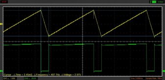
Yes, the output does does go to zero for a period of time. No, you never want to discharge the the capacitors more than a few percent. Speed control approximates this but super hard to modify. An inverter is a much closer match. I've been heating with PV for years. Here is a scope example. The triangular waveform is the capacitor bank charging and discharging. This is only a couple volt difference on over 60V. The low portion of the green is when the element turns on. Note the capacitor discharging. Anyone want to actually do this. Only those serious and have a good technical understanding need apply. 60-130V arrays only.HWBnew65W_17ms.jpg
 
I was going to throw in, my dad uses one of these: http://www.cyboenergy.com/products/cimini1200h_overview.html and you can call them and have the main designer/engineer program it to do almost anything you want.

I was going to inquire if he could program one to only smoothly dump energy above a certain voltage threshold on my 14S battery into a pre-heater hot water tank. That way once my battery gets over ~57V, just dump into water heater.

If that thing delivers an AC sine wave of variable amplitude, whatever is necessary so resistive load takes 100% of available PV energy (and it tolerates thermostat opening), then it is ideal!

Thank for that link!

"Nominal Operating AC Output Voltage / Range 100V – 240V (10V – 264V, Single-Phase)"

Certainly appears to.

Only downside to this sort of system is that if you don't use PV to heat water because tank has reached max temperature setting, you lose available production.
For my case, what I would like is something powered by AC, varying amplitude of AC voltage fed to water heater in order to use surplus PV (keep battery floating.)
 
I could probably hack something together with dimmer switches and some voltage dividers with the battery :p

I want to make a liquid to liquid heat pump with two large buffer tanks for access to cold/hot depending on the season and thing. A hot water/hydronic heating coil, an AC coil, and then have an air/liquid heat exchanger depending on whether you needed to bring more heat in after the heat pump fluid circulated through the chilled side, or dump excess heat after circulating through the hot side depending on the season. I'm going to screw around with making a pump myself after reading this thread years ago: https://ecorenovator.org/forum/showthread.php?t=484

After I saw this video
a few years ago, I thought, why do we have only air based or ground based heat pumps? Why don't do a large black body panel, at least for heating? I then came across a bunch of Chinese vendors that make stuff like this: https://www.alibaba.com/product-det...offerlist.normal_offer.d_title.7bc36e0cMHzsTR ,that do exact that! I haven't found an American company. Although someone could probably use a liquid to liquid geothermal heat pump with those dual PV+liquid circulated solar panels that are here or there.
 
Last edited:
I could probably hack something together with dimmer switches and some voltage dividers with the battery :p

How do you plan to use the dimmer switches?
They make nasty waveforms, sharp rise to some point in the AC waveform, then ride it to zero.
I've thought about that as away to vary heating loads but it would jam a lot of harmonics onto the AC line.

I do have a variac, which could be motorized, but limited power handling and it's part of my lab equipment.
I was mostly joking although I know in the past they just PWM'd the AC waveform, so wayyy ugly. I don't know what the nicer LED ones do now. One that I took apart like 20 years ago just had a potentiometer slider thing that caused it to vary the output, so if I had one still that way I could probably figure out a voltage mapping using a voltage divider with a reference from the battery.

I have a raspi connected to everything now, so another half-baked thought is if there is a class-D audio amplifier that I could generate a simple AC waveform from the pi and vary the amplitude based on what my CT's are reading.

My main point being if you meant to use them with DC, SCR would turn on and never turn off. (which you probably knew)
If with AC, sure, a servo simulating that potentiometer could control it based on the input signal (AC frequency in the case of my Sunny Island)

Current transformer is half the info, need voltage too in order to determine direction of power. Are you considering this for zero export or some other purpose?

I've had some LED which claimed to be dimmable, but they flickered. It would take a more sophisticated LED drive circuit to be backwards compatible with dimmer switches.

I have tried using relays to connect heating elements series/parallel for a range of wattages, but my relays twisted and shorted the rails. I'm not using them in a more limited way, with the surviving contacts.
I was mostly thinking out loud about your interesting problem of varying the AC into the heater based on your battery SoC and the energy going into the grid.

I have a growatt 12000t right now, mostly sized to meet peak load during the summer with the AC running and all the kids on computers, but during the winter the inefficiency of the inverter heats the single garage where all my stuff is (including the battery), so I planned to just use smart power devices to have some logic on the raspi switch on the electric element in an electric water heater before my main one as well as some 300W outlet room heaters around the house.

On sunny winter days there is more then enough, but on cloudy I pretty much just switch to grid and let it build up the battery to use every third day or so.

I was going to just use a dump load controller like http://techluck.com/wind-turbine-pwm-dump-load-controller.php or https://www.altestore.com/store/cha...ollers/diversion-dump-load-controllers-c1022/ directly into a heating element, but now I'm not so sure.

Oh, and I get the power the house is using via modbus rtu from two 1kw grid-tie inverters with limiters that I still have (one of them doesn't see any voltage on the input anymore). I want to replace those with reading CTs and grid voltages myself with the raspi
 
Sunny Island runs frequency up from 60 Hz to request reduced power production. It knows SoC so this is better than just voltage based.
Sunny Boy linearly reduces power output from 100% of what's available from PV at 61 Hz to 0% at 62 Hz. So frequency communicates not just the fact battery is full (or is absorbing all it can), but also how much PV power is going to waste.

A circuit which took in 240VAC and delivered 0VAC to 240VAC as frequency ramped from 60.5 Hz to 61 Hz would let a heating appliance make use of as much surplus power as it could take. Beyond that, the Sunny Boys would be asked to reduce power.

The servo-controlled dimmer switch might do it, with all transformer based inverters that might tolerate the high harmonic power / poor PF from the dimmer.

I'd rather have a switcher that drew sine wave current and delivered variable sine wave output.

When I tried varying my pool pump with VFD, a transformerless Sunny Boy reported an error. Front-end of VFD is rectifier/capacitor, not PF corrected.
Varying pump speed is another way to utilize the surplus power. My VFD has an analog input.
I only have so much need for filtering. Variable speed well pump would be good for people without city water.
I bet the cyboinverter people could do that, although imo it is a little expensive, although American supplied and supported - you can talk to the man who programs them to do whatever you want.
 
Is there any off-the-shelf stuff you guys know about that one could set up a mess of solar panels and magic box 1 and maybe a magic box 2 and directly drive a 240V 4,800W standard water heater element?

Any ideas welcome.
Yes ... a dc to ac inverter, the hot water heater will work on dc but the thermostat and safety cutouts won’t last long. Don’t forget that there is a limited period of time for electricity production.
 
I thought she said she wanted to run a water heater ! She didn’t say for how long and water heaters don’t care about frequency and are tolerant about voltage.
 
Yes, the output does does go to zero for a period of time. No, you never want to discharge the the capacitors more than a few percent. Speed control approximates this but super hard to modify. An inverter is a much closer match. I've been heating with PV for years. Here is a scope example. The triangular waveform is the capacitor bank charging and discharging. This is only a couple volt difference on over 60V. The low portion of the green is when the element turns on. Note the capacitor discharging. Anyone want to actually do this. Only those serious and have a good technical understanding need apply. 60-130V arrays only.View attachment 35043
Appreciate the feedback. I've been playing with this off and on for the last year. Currently I'm up to 1200 watt (4x72 cell panels) in series/parallel. I was going to run them all in series and push about 150v into the element but was trying to use DC SSR to do the switching. The issue is they keep blowing and shorting out. I'm only powering the bottom element and I pulled out the 220v element and run a 110 element to better match the watts. Aside from not being able to switch the power I can heat the 50 gallon tank to >180 in the summer and >140 in the winter. So we actually have to use hot water to keep the temp down. hee hee hee. If I could only switch it I'd be happy. I'm using the water heater thermostat to turn off/on a 12v dc power supply and that triggers the SSR. The SSR is rated 5-60 vdc at 40a. I'm pushing the voltage but well under the current rating by more than 50%. So I purchased a DC motor speed controller to try and get a zero crossing pulse so i could use the water heater thermostat but have not tried it yet. I just purchased a mini hand held scope to try and see the wave forms you supplied.
 
Back
Top