diy solar

diy solar

Direct to water heating.

How much is it?
Would be good for a domestic company profiting from their innovation, before knock-offs appear and kill the off.
Main concern I have with this sort of device is power only gets used for heating, so when surplus gets wasted.
 
I think everyone should watch Mike Holt's videos on grounding and bonding. Especially the swimming pool video to understand the principals of bonding. Power can short to the pumps frame and still the pool is safe. It is a lot to take in and can be confusing. Even Mike tells you not to do something and in another video he will do just that. If you feel a heating element can be a danger in your house then no metal in your house is safe to touch. Your inverter provides exactly the same 200V DC path as the water heater element would. An isolated power supply wouldn't really provide extra isolation.

2,000W would be expensive using a power supply. I have had Europeans asking to design a boost technology for their single element 2,000W 230V heater element on 120V DC systems. Boosting that with a power supply would be practical. Older MSW inverters would be a practical way to produce AC for a phase triggered system. The inefficient boost inverter section can easily be bypassed and the HV DC can be feed in directly with a triac changing duty cycle. A capacitor bank and isolating diode will still be needed to make it efficient. Energy must be stored in the capacitor bank during the off cycles. With solar panels you have to use the energy or loose it forever.
The big difference is that you're bare feet in the water when under the shower making this place more dangerous then to be near the inverter with boots.
The problem is not the 200V, it's the fact that it is DC and that we do not have differential breakers to detect a current leak. The water tank ground could be rusted, unscrewed .. or i do not know what ... and then the risk is real.

Since the capacitors are mandatory for an efficient system .. why not changing ouput voltage to make it less dangerous (hence the 48V) then a 200V input.. or is there something i missed.
 
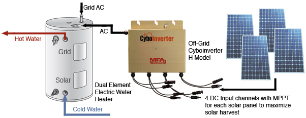
I know this has already been cited, and it is expensive, but I love what http://www.cyboenergy.com/products/offgridHmodeloverview.html does in that they simply vary the AC voltage according to the actual solar output. Someone should really contact one of these Chinese inverter manufacturers and suggest they make an option in their firmware to do the same thing, then eventually a bunch of them would be on the market for cheap.
It's on grid ... if i'm not mistaken.
 
Not sure if i posted this already, but this one is commercially available for those wanting a professional solution.

Especially in Australia where used PV is free or very cheap - it is a good option for hot water.
 

Attachments

  • 3555731D-31F2-43EA-986D-D1B614E12C73.jpeg
    3555731D-31F2-43EA-986D-D1B614E12C73.jpeg
    177 KB · Views: 14
Not sure if i posted this already, but this one is commercially available for those wanting a professional solution.

Especially in Australia where used PV is free or very cheap - it is a good option for hot water.
I never seen this one, thanks for the info.

I looked pdf and It say that it need a 48v PV array, which is not flexible, and for 800€ it look like pretty expensive to me. What I mean, but I'm perhaps wrong is that a all in one Chinese inverter will do the same for 250€, 3.2kw inverter with mppt and battery charger.
 

Attachments

  • Screenshot_2021-11-30-08-36-51-129_com.lonelycatgames.Xplore.jpg
    Screenshot_2021-11-30-08-36-51-129_com.lonelycatgames.Xplore.jpg
    226.4 KB · Views: 7
I fully understand what you are trying to say and I'd rather you be over protective when it comes to electricity. So many here are too caviler in playing with something they don't understand at all. I don't care how you heat water. I've pretty much given up on solar people figuring out how to do it. You just can't get your pseudo science from the cinema and broadcast it as fact. There has to be a current path. You mentioned that you can't trust your ground and that can be a serious problem.

Years back there was a little girl electrocuted when she tried filling her bucket from an outside faucet. There was a floating neutral from the grid. This is a far more common problem with the utility than you think. A year ago, a tree took down my utility feed and they replaced it with new wire. I had tried getting them to do that for years because i was 70 years old with no insulation. Seven months later my lights are starting to flash and the microwave would go crazy. Down at the fuse box I could see an imbalance of more than 30V. I then look at the connection to the house from the street and I can see tape split on the connection from heat. Call the utility and the guy pulls each of the three connections from the crimp made by a power tool. I was fortunate that I had copper pipe to the street. That provided sole limit on how high the imbalance could get as that could conduct some current. My galvanized shower drain pipe had been replaced by plastic. GFI wouldn't have saved me. The cast iron sewer pipe would have provided a separate ground path from the water pipe which now had voltage. Mike Holt even discussed bonding in this shower issue. There are potential paths you are not even considering even with the setup you are considering.
 
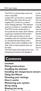
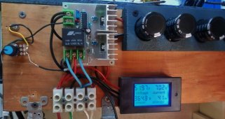
this seems like a nifty waterheater controller.
only thing that has be baffled is the PWM and mppt used both ..

any ideaa on it's validity ?

 
GFI wouldn't have saved me.

Because neutral was hot? A "portable" GFCI, interrupting both hot and neutral, might do it.

Come to think of it, a DPST relay downstream of single-pole GFCI, interrupting both line and neutral when power goes away because GFCI opened hot, should implement a both-poles GFCI.

But isn't your water heater fed 240V, L1 and L2 not N? I that case, 2-pole GFCI. I've got one of those on my dryer circuit (which does use neutral)
 
this seems like a nifty waterheater controller.
only thing that has be baffled is the PWM and mppt used both ..

The MPPT circuitry is to keep the panels at their optimum voltage.

The PWM is to chop the DC to prevent arcing in the thermostat.
 
The MPPT circuitry is to keep the panels at their optimum voltage.

The PWM is to chop the DC to prevent arcing in the thermostat.
ah thanks, now it makes sense...
still wondering if this gizmo works as advertised though...
it would be a great addition to my hot water set up ...
have been looking really hard at loadmaster XP, but have had no time ( other prio's ) to build it


wonder if the device is about the same just assembled
 
The PWM is to chop the DC to prevent arcing in the thermostat.
That is not true. While the PWM chops, I do not think it has an arc interrupt routine. That is why it has an external temperature sensor. The device also requires external isolated 12V DC power. Connect this to your 12V battery and there will be trouble. Many electronic wall warts which have a switching power supply can supply enough power to run this with only 70V DC supplied to them. I have never personally seen one, but zeppole left what I thought was a reasonable assessment. I have followed him on other boards and he stopped posting and just disappeared after getting a lot of nasty comments on his review of this unit I've been meaning to email him if he has any updates on the unit. You don't really know what is in all these other boxes or what failure mode they may have. There is always a path that should never happen.

A point I am trying to make is that any time there is HV somewhere in the system, there is always a possible path to you. Not only has to be a path to you, but a return path. Things are made safe by multiple interruptions to that path. I would have no issue with taking a shower after a ground was removed from my water tank and the case connected to HV. There is no electrical connection made between the copper pipes and the water heater. There is an electrical insulator between the pipes and the tank. Most tank connections have these to prevent electrolysis. Mine are a little bigger. Even UL seems comfortable with heating elements with metal shields that are not connected to the tank. There are videos on youtube where they throw a hair dryer with a GFI into a sink of water and it just keeps running. Mythbusters threw a toaster into a bathtub of water trying to electrocute a dummy. There were no flames like in the movies and the dummy didn't die. A voltage gradient in the electrical path has to be created. Understanding this and looking for possible paths will keep you safe.

Not being able to depend on a ground is the worst case, that little girl trying to fill her watering can. If 20 people drive a rod 20 feet from their home it is likely that one will see 10V between that rod and their home ground. I was in an industrial building and looked up to see some steel stock leaning up against the metal building support and the cast iron sewer vent pipe. Sparks were shooting out between the stock and the vent pipe. I was asked if I wanted to fix it. NO! A year before they had a professional engineering firm solving this problem. It was low voltage but a lot of current, I moved the metal.
 
The MPPT circuitry is to keep the panels at their optimum voltage.

The PWM is to chop the DC to prevent arcing in the thermostat.

An MPPT SCC is PWM and an inductor drawing approximately steady current from PV panels (probably with a capacitor on PV input)

An MPPT water heater controller is PWM, no inductor needed. It just draws square wave from capacitor on PV input.
 
ah thanks, now it makes sense...
still wondering if this gizmo works as advertised though...
it would be a great addition to my hot water set up ...
have been looking really hard at loadmaster XP, but have had no time ( other prio's ) to build it


wonder if the device is about the same just assembled
Mmm this one look nice ..
 
I forgot to talk about the Loadmaster. It is a design made by a software guy and some of his claims are a little iffy. I don't think it works as well as he says because he hasn't really tested it, just made guesses. Rather than losses in heat, it might not be able to transfer all the power the panels are capable of creating. Analysis of the AC component of the input would be needed. Solar panels are current sources. Panel current changes over a short period of time indicate the circuit is not able to store or use all the power a panel can create. The techluck claimed "97% (pass thru)" which is saying when it is not actually functioning at full power. Nothing was ever said about 50% panel power efficiency or any other range. It has three capacitors the size of your pinkie to store energy and provide all that current to the heating element. I just wonder how long those can last running all day for years being rated at .58A. Internal heating will dry them out. The internal welds of a capacitor are the weakest part. Often these are just a crimp. Repeated current spikes can cause them to fail. The standard rating for capacitors at temperature is 4,000 hours. Physical size and current rating of capacitors does matter. Sure would like to see a thermal scan of those at 50% power. There are differences in design that mean more to me than others. All these designs should work well enough to gain extra power over direct connect. The techluck which might never appear again had a severe weakness in the power supply making prone to extreme failure from a near lightning strike. I worked on
one and the only semiconductor on the board that didn't fail was the reverse voltage protect diode. For that owner it was a total loss. The ACTii solved this issue by making the power supply a seperate item. Really nice small packaging which makes it cheap to ship. Even though the photo boost module may have some length of life issues because of size, these would be easy to repair and make even more robust. Current is limited to 8A because it is made for a european marker where water heaters are smaller and lower wattage. I designed my board for 10A and that is only limited by the capacitor bank for convenient physical board size. The ACTii uses a fan because of its small packaging. Fans are always a failure point.
I use two FET in parallel which reduces heat by four times that of just one. In normal operation there is no noticible heat rise. The techluck also is 8A and uses a IGBT which has a high saturation voltage causing 15W of heat. Unknown if ACTii uses IGBT or FET.

Those with small camps don't realize that they can add hot water with a very minimal investment using only excess power from their existing array. A small array will possibly need only one or two extra panels. No need for for a battery or increase charge controller or inverter capacity. A common 6 gallon 120V water heater doesn't need the element changed and can heat water with only one KWH of energy a day. I use a 50L (13 gallon) tank from China that was only $150 shipped. It meets my needs and I have a dishwasher. Cheap, but needs extra insulation to make it effective. I gave up my propane heater years ago. I was refilling several tanks each summer. Waking up and having hot water at the sink really changes the camping experience and it costs next to nothing. This idea just has not gained acceptance as this group are usually beginners. You do need to use an array of 60-90V and they are usually battery voltage systems.

The ACTii is capable of operating in two modes. Full MPPT in a stand alone system or as a fixed voltage power diverter. The fixed mode has to be used when in parallel with a charge controller as two MPPT would fight each other. The voltage can be ajjusted seasonaly to account for temperature. My board has an external temp sensor that can be attached to a panel or a small square of metal exposed to approximately the same sun conditions. This calculates the natural power point.I was amazed at how many want to have stand alone hot water systems which to me seems very wasteful. Any successful PV system has to have excess power to recover from bad days. Why waste that power. These systems are amazing to see operate
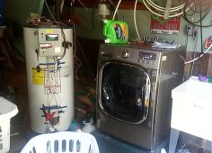
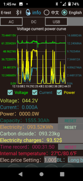
and once you have used one would never be without one. The picture below is a half hour graph of my garage system. It uses only excess power not used by the house system and the house water heater. This 40 gallon water heater in the garage is only for the laundry and only hot water is feed into the cold inlet of the machine so all cycles use hot water.

This is a 60V array and at temperature the MPPT ideal voltage should be about 57V. This parallel array has a lot of shading and you'll see it drops to 44V at the very end, likely the refrigerator has turned on. I set the fixed voltage (green trace) higher to insure the house systems have priority. The garage also has two panels facing east and the distance to the house systems
is about 125 feet. The higher voltage insures more power goes to the house in the morning. I could be more agressive, but I get adequate hot water as it is. The dips are from clouds and/or demands on the house MPPT charge controller. Peaks above 61V are because the two 5500W elements in parallel can not take all the excess power available. Since it peaks out at less than 5A, the upper thermostat has opened up leaving just one element. Again I could be more aggressive and replace the heater elements with lower resistance ones. The clothes come out of rinse cycle steaming so why bother. I have a LG front loader and these are notorious for the mold problem. The detergent dispenser is always spotless. At home I have the same machine and have to pull the dispenser apart and clean mold out of it periodically. I should do full hot water at home. Blue trace is the element current. Yellow is the heater power. Notice given varying cloud conditions in this half hour view excess power is instantly delivered to the water heater or removed. It makes this decision up to 100 times a second. The washer in the garage also runs off these panels with no battery. When the washer goes into a low current fill cycle, excess power goes back to heating water. Free laundry is pretty neat although it has now become my responsibility to do it. In the event of a large cloud, the washer will stop. I'm generally out in the garage working so that isn't a problem. Just restart it when the cloud passes. That doesn't happen often. We line dry and only do laundry on really nice days. Last picture is the laundry system in the garage. You are not seeing things! Those are jumper cables connected to the water heater. The 10A pulses are ideal for desulfating a lead battery. Battery is in series with heater element. I just clip them together when I don't have a battery. I've been picking them up at the town recycling and experimenting with restoration. Our town has a lot of people who ignore batteries over winter and just buy new ones. Been lucky, can't save them all.

Tall tanks are really the way to go. The top 15 gallons heats quickly and the lower section acts as a pre heater. This stratified heating method has drawn the attention of adaptive control builders as a way to economize tank performance. Lower tank heat loss drops to almost nothing due to temperatures not much more than ambient. Larger 40 gallon tanks are almost the same cost as less popular small tanks.
 

Attachments

  • ACTii_AC7391_review.jpg
    ACTii_AC7391_review.jpg
    94.8 KB · Views: 11
  • GarageLaundry.jpg
    GarageLaundry.jpg
    178.5 KB · Views: 11
  • DIVERSION_21-09-22.png
    DIVERSION_21-09-22.png
    111.9 KB · Views: 11
It's on grid ... if i'm not mistaken.
They program the same core to do multiple things, including supplementing grid AC loads without feeding into the grid. However, they have a specific application where it is purely off-grid. It still inverts the power battery-less, but because a heating element is a purely resistive load, it simply varies the voltage of the waveform to match the power output from the MPPT. The reason they keep it AC is so that it can be used with lots of unaltered AC based resistive heating (thermostats).
Hmodelsolution.jpg


(note: I don't represent them, just a fan of their products and have followed them for a few years; My dad bought a couple of their inverters a couple of years ago and they have been great)
 
Last edited:
They program the same core to do multiple things, including supplementing grid AC loads without feeding into the grid. However, they have a specific application where it is purely off-grid. It still inverts the power battery-less, but because a heating element is a purely resistive load, it simply varies the voltage of the waveform to match the power output from the MPPT. The reason they keep it AC is so that it can be used with lots of unaltered AC based resistive heating (thermostats).
Hmodelsolution.jpg


(note: I don't represent them, just a fan of their products and have followed them for a few years; My dad bought a couple of their inverters a couple of years ago and they have been great)
Hoo i did not seen this one, but in fact it's just an inverter and they cost a lot (700$ ?). My 5kW batteryless inverter cost me 400$
a 3kW one cost 300$.
 
Hoo i did not seen this one, but in fact it's just an inverter and they cost a lot (700$ ?). My 5kW batteryless inverter cost me 400$
a 3kW one cost 300$.

Difference would be that this inverter meant to drive water heater varies output to maintain PV at MPPT.

It could be done as cheap as an inverter, cheaper even because it can be PWM with no inductor. But volume production is lacking.
Maybe for someone with particular power needs and solar availability would find it a good value. $700? Same as electric water heaters now cost in my area, so anything cheaper gets into asymptoticly approaching water heater cost for total system cost. (Assuming same life span.)
 
It is a shame they are so expensive. China should be offering these for $70. There is just no demand. I made one out of a $7 inverter board and am still using it even though I've made better. Just surprised there isn't a community of people building these or even talking about it. This is DIY.NHW01.jpg
 
Last edited:
Anyone know of any inexpensive inverters for which someone has hacked their firmware?
 
Any old MSW inverter would be easy to hack using just the H bridge section. You feed array voltage into the HV caps and provide 12V to the control circuitry. Most old inverters use a TL494 to generate pulse widths. I've used anywhere from 20V to 140 to power them. Circuit just doesn't care. Add extra capacitors to the array to store power during off times to make it efficient. Just change the circuit for constant array voltage. As electronics goes it is quite simple. If this makes your head spin, there isn't really any help I can give you. There are hundreds of inverters and they are all slightly different. The output sections are quite robust. a 1,000W inverter could easily power 2,000W into a heating element with no heating issues.
 
Back
Top