diy solar

diy solar

Dirty power since trying to deploy Trace inverters (not the inverters’ fault)

idoboats

Solar Prepper
Joined
Aug 17, 2020
Messages
17
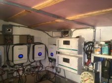
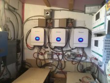
I just installed two Trace sw5548s. There is a 60kw lifepo4 battery bank hooked up. I am running it off grid, no a/c input. I have the ribbon cable installed. I measure close to 120v from each inverter, 240v between the two hots going into a box that goes to a manual transfer switch in my house. I measure the same voltages at the transfer switch. I am having trouble powering my loads. I know that the inverters don’t have a true sine wave. Could there be something wrong with them where they are no longer delivering their rated amps? I am tentatively trying different loads. It seems that the Mr Cools are ok and even the TVs, but the dryer didn’t like it, nor did the Sub-Zero, and some of our led lamps fluxuated between from not so bright andvery dim. When I first flipped these inverters on, I did so more aggressively and blew power strips and tripped gfcis (also got the over current light on one Trace). Thank goodness my wife’s fancy robot vacuum was on a surge suppressor. We have been using Growatts to power all of the above loads with few problems. I already owned the Traces and wanted to add them to our system. My strength is more in the installation phase. I always cringe when I got to turn things on and make them work.
 
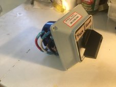
I have been experiencing dirty power since my new install. I thought it might be the Trace inverters since they don’t have a true sine wave. Since then I switched back to the Growatts and I experienced the same dirty power symptoms including blowing out some led lights. When I added the Trace inverters I installed a barrel switch so I could switch between the two sets of inverters (either one or the other could then power the panel that is run into the manual transfer switch in our house). I can’t think of anything else I changed except for some grounding that I am trying to finally get right. The Growatts never made any of our loads act like they had dirty power until after my latest “upgrades”. I plan to disconnect the barrel switch to see if that helps. Please chime in if you see electrons better than me.
 
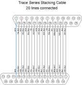
I assume you are sure you have a series stacking ribbon cable and not a parallel stacking ribbon cable. If you have a consistent 240vac between two inverter output hot lines you have correct series stacking cable.

You must have the two inverter's neutral wire connected in common. Any 240 vac load current flows through neutral connections.

Trace Serial Stacking.jpg
 
Trace : anything with that name on also has some serious years on it - the huge electrolytic caps (at a minimum) are ripe for drying out & decrease in capacity, at least they are stand alone and easy to test / replace...

I've also seen where over the years repeated condensation drips have reached the main board and corroded axial resistor(s) to the point one went open circuit and the unit was scrapped (thats how I got it) so keep 'drip loops' on wiring in mind...
 
Last edited:
Just another FYI, if you have a 240vac/120vac generator connected to AC input the two inverters will follow the generator phasing and the series stacking cable is not keeping phase at 180 degrees. It is not until inverters are running on their own that the series stacking cables provide the 180 degree phase syncing.

The series stacking cable is also supposed to cause both inverters to shut down if either unit shuts down for any reason. I have seen this not work with different softwave versions on the two units. You should check that the two units have the same SW revision. It shows on the menu screen 3 'Trace Engineering 3', third sub-menu down readout.
 

Attachments

  • SW User Menu.pdf
    1.5 MB · Views: 5
  • SW Setup Menu.pdf
    1.8 MB · Views: 7
Trace : anything with that name on also has some serious years on it - the huge electrolytic caps (at a minimum) are ripe for drying out & decrease in capacity, at least they are stand alone and easy to test / replace...

I've also seen where over the years repeated condensation drips have reached the main board and corroded axial resistor(s) to the point one went open circuit and the unit was scrapped (thats how I got it) so keep 'drip loops' on wiring in mind...
I have pretty much the same thoughts, the filtering caps are likely dried up just for starts but I thought Trace's had good sine wave ouput.
 
I think you really need to connect up an oscilloscope and look at the actual waveforms.
The Trace actually has three inverters inside, connected in series, to generate pretty close to a sine wave.
At least its as close (or better) than what you get on the grid these days.
One of the smaller inverters may have died or have a problem, and you will still get almost full output voltage and power, but the waveform can become very distorted.
 
The barrel switch is highest box. Hertz as measured with multimeter is high and variable.
I assume you are sure you have a series stacking ribbon cable and not a parallel stacking ribbon cable. If you have a consistent 240vac between two inverter output hot lines you have correct series stacking cable.

You must have the two inverter's neutral wire connected in common. Any 240 vac load current flows through neutral connections.

View attachment 128069
Thank you. I will be verifying pins from this diagram.DB924062-AEA8-4692-AC1D-2D2BF2546E4D.jpeg
 
I really appreciate the help I’m getting. I will investigate the filtering caps. I had tested these inverters before installing, but I didn’t push them hard. They seemed ok. Because I am also having the same symptoms when I switch to the Growatts, I am suspecting that there is a problem in my installation. I will post what I do and my results, but I need to get to it.603BD113-06ED-4E02-994C-16BBCA068FE6.jpeg
 
The three inverters (15v, 45v, and 135v) are shown up in the top left hand corner of your circuit.
If the 15v inverter, or even the 45v inverter has a fault, that can really distort the waveform, although the measured output voltage will not change as much as you might expect.
 
Are you running the trace inverters in parallel with the growatts for added capacity?
 
Are you running the trace inverters in parallel with the growatts for added capacity?
No. I installed them as separate systems, but they share the batteries and panels. I switch the panels using Anderson connectors. I have Midnight Classics for when the Growatts are shut down. The barrel switch is meant to be able to switch back and forth between the two systems and a common load. I owned the Traces and one of my four Classics and wanted to incorporate them into my project. I worry about relying on the Growatts and want to be able to quickly get up and running if something happened. I also plan to run with them for a while to get used to them. I’ve learned that having the parts stored is not enough.
 
The three inverters (15v, 45v, and 135v) are shown up in the top left hand corner of your circuit.
If the 15v inverter, or even the 45v inverter has a fault, that can really distort the waveform, although the measured output voltage will not change as much as you might expect.
Thanks for your input. I suspect you are referring to the Growatts.
 
Thanks for your input. I suspect you are referring to the Growatts.
No its the Trace/Xantrex inverter that has three separate inverters inside. Look at the circuit of the Trace power board you posted earlier.

Up in the top left hand corner you will see the three mosfet power bridges and three transformers that produce 15v, 45v, and 135v.
These three voltages in the respective secondary windings are connected in series and are added together.
If one of those smaller inverters goes faulty, its no longer possible to generate a nice clean 27 step sine wave across TB3.
What you get is still likely to be pretty close to 120v, but badly distorted.

You really need an oscilloscope to see the nature of your "dirty" power.
 
Last edited:
Today I removed the cam switch and took the Traces out of the equation. With the Growatts I am reading 60 hertz with no load, but when I apply a load it starts off ok but then starts to fluctuate and is jumpy and seems to get worse. I checked the settings of all 4 units and they all read 60htz. I am using an outlet wired directly to the panel the Growatts feed in the power shed, and running a 660w heat gun. I am getting spikes in hertz in the 80s. I am wondering what in the Growatts regulates the frequency under load. Could I have damaged that part? They worked before my “upgrades”.image.jpg
 
No its the Trace/Xantrex inverter that has three separate inverters inside. Look at the circuit of the Trace power board you posted earlier.

Up in the top left hand corner you will see the three mosfet power bridges and three transformers that produce 15v, 45v, and 135v.
These three voltages in the respective secondary windings are connected in series and are added together.
If one of those smaller inverters goes faulty, its no longer possible to generate a nice clean 27 step sine wave across TB3.
What you get is still likely to be pretty close to 120v, but badly distorted.

You really need an oscilloscope to see the nature of your "dirty" power.
Thanks for clarifying. I will be testing the Traces again now that I’ve identified the dirty power problem on the Growatts. I don’t yet have an oscilloscope, but with the issues I’ve been having this may change.
 
Back
Top