diy solar

diy solar

Distribute demand system

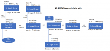
If I have followed the description so far, this is my understanding.

1666567046627.png

I am thinking that since the cell/wifi will be a 24/7 draw, it makes no sense to convert it to DC and back. It would be better to run it off the 240 directly. Consequently, unless the windmill goes in, there is no need for a battery or inverter at site 3. However, for planning, we will need to know the current or wattage the equipment will draw.

Could you provide a max wattage the inverters at 4, 5, 6 & 8 will need to handle? (I am assuming there will be tools that need power in the workshed.

Are there any other refinements you can make to the above?
 
At the small draw sites, if the max wattage needed is small enough, it might be just as efficient to just have a 12V power supply hanging off the 240V. Alternatively, if it is just LEDs and power bricks for electronics, maybe it is better to just run them directly off the AC. (You can buy 240V LED fixtures)
 
You are dead on correct.

I completely agree about the usage at 3A. Any DC demands here are USB-connectable/chargeable so I would just wire in a USB outlet box to the grid and plug it all in there.

Demand can be ignored #5. Short-term it will be none or minimal. Long-term it will be so close to the batteries as to not matter. I am less concerned about the specific hardware choices as I am about ensuring the interconnection wiring is affordable and hardware is commercially available.

Please clarify the supply line here. When you say 240V are you talking about standard household service with +120V/-120V/neutral 3-wire connection or something else? What are we using as acceptable voltage drop?
 
Please clarify the supply line here. When you say 240V are you talking about standard household service with +120V/-120V/neutral 3-wire connection or something else? What are we using as acceptable voltage drop?
For the high draw site interconnects, I am hoping we can find equipment that allows us to just use a single phase 240V (no Neutral) on the pico grid.

For the low draw sites, I am pretty sure we can just use the single phase 240 without neutral.

I am using 3% as the max allowable voltage drop in my calculations. You could get away with a voltage drop as high as 8%, but that also means there would be more line loss (lower efficiency). (An 8% voltage drop on 240V brings it down to 220V. Just about all 240V equipment will run just fine at 220V, but at 3Amps, that is a 60W loss. (1.44KWh/Day!) It may still be better (Lower cost) to have a few more solar panels and run at a higher voltage drop. As we get closer to a final design we can play with the trade-offs between less copper and higher efficiency.

Note: When we get further along, you will have to decide if you want to run an equipment grounding conductor along the pico-grid. In general, I would recommend running the EGC, but there are a lot of different factors and some folks might choose to forgo it. We can go into all this later.
 
That makes better sense. I thought we were at 240 3-wire and the wire size looked unreasonable. I make this at 2.6% loss in 10 gauge @ 600 ft. For the purpose of discussion I can get 2-conductor+ground UF-B for $0.53/ft at my usual place.

For the sake of discussion, I originally came in hoping something like this would work:

View attachment 117579

1666580978131.png
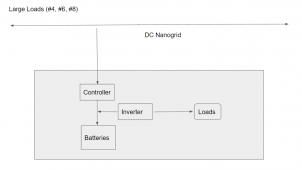
Basically hoping to reduce hardware count by wiring batteries in series to something in the 240 - 560V range, running the DC grid directly connected to the batteries, then converting at the point of use to 120 AC, rendering voltage drop moot.

Don't know enough to know why that is not practical, though I assume it is not, and I assume there is no reasonable way to backfeed from sites, but the savings in wire and hardware might pay for a few extra batteries at the main site.
 
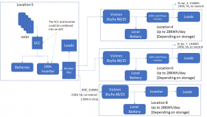
Well.... I looked over the Victron inverter/chargers and did not find anything that would do what we want for the unidirectional solution I talked about before. However, I looked at their chargers and it looks like the Skylla-48/25 charger might work well for an arrangement like this:

1666581526834.png

You would want to shop around to see if there are other chargers that would work for you. One nice thing about doing it this way is that there are not a lot of requirements from the pico-grid on the inverters.
 
That makes better sense. I thought we were at 240 3-wire and the wire size looked unreasonable. I make this at 2.6% loss in 10 gauge @ 600 ft. For the purpose of discussion I can get 2-conductor+ground UF-B for $0.53/ft at my usual place.

For the sake of discussion, I originally came in hoping something like this would work:

View attachment 117579

View attachment 117583
Basically hoping to reduce hardware count by wiring batteries in series to something in the 240 - 560V range, running the DC grid directly connected to the batteries, then converting at the point of use to 120 AC, rendering voltage drop moot.

Don't know enough to know why that is not practical, though I assume it is not, and I assume there is no reasonable way to backfeed from sites, but the savings in wire and hardware might pay for a few extra batteries at the main site.
Hmmm..... running the DC at very high voltage works, but then you would need a very high voltage inverter or a DC-DC voltage converter. I have never looked for or used inverters or converters that run at those voltages. I am sure they exist for industrial applications but they are going to be hard to find for this size application.
The other thing to consider is that switching high-voltage DC is tricky because of the possibility of a sustained arc. Consequently care would be needed in selecting breakers/fuses and disconnects.
 
@FilterGuy - Do I understand correctly that I am basically using European equipment to run my grid at European standards then using the Skylla/Inverter pair as a bridge to American standards? I had not thought of that. Clever and inexpensive. My hat's off to you.
 
I think something like I show in post 28, could be made to work, but it is going to require more batteries.

I still think an investigation into AC coupled inverters is needed. It may allow bi-directional power flow and therefore fewer batteries.
 
@FilterGuy - Do I understand correctly that I am basically using European equipment to run my grid at European standards then using the Skylla/Inverter pair as a bridge to American standards? I had not thought of that. Clever and inexpensive. My hat's off to you.
yes.... kinda....but not really. The inverters can all be US (even the 240V ones). The Skylla has a universal input so it is international. The trick is that the Skylla does not need neutral...... so we don't run it across the pico grid.

I was thinking about this more and I realized that even though I was not thinking of it as using EU standards, you may be on to something.

I was thinking of using a standard US inverter at site 5. This means the 240V consists of two hot wires and a neutral. We would not route the neutral over the pico grid so the pico grid would not have a grounded conductor. This works but it presents a few grounding issues.

If the inverter at site 5 is changed to follow the EU standard, it would have one neutral (Grounded conductor) and one hot that runs at 240V between them. This is much better for routing across the pico grid (Particularly if you decide not to run a grounding wire). The downside of this is that unless there is a 2nd inverter at site 5, 120V would not be available.
 
The Victron chargers are pricy so you may want to watch this thread:


Note: Victron is definitely pricy, but everything I have ever used from them is rock solid. (Their main market is the high-end boat industry and boaters can not have system failures when they are hundreds of miles offshore)

Also, I notice that there is an accessory to the Skylla that allows you to adjust the current in down. This would allow you to tune in the amount of power coming in over the line.
 
I'm more interest in "rock solid I don't have to think about this for 20 years" than saving every last dime. I'm old enough that anything I do from here on out, I only want to do once.

What I really like about the Victron is the wide range of input voltages so if I underestimate needs at a location I can just draw more and live with a few extra percent of voltage drop and efficiency loss of the feed while keeping branch voltage where it should be. If I calculate this right, I could plan for 5A on 10 gauge at 600' with under 3% loss, but could run that all the way up to the 30A rating of the wire and still be within specs for input voltage. Big loss in efficiency, but it would still work in a pinch. I think this idea is the winner.

I had assumed site 5 would have its own connection to the battery bank, separate from the inverter system for the grid, for 120 use. That site is likely to have very power-hungry equipment and I'd rather keep it isolated.

I was planning to run UF-B for the grid, so that gives me two conductors and a ground.
 
Back
Top