diy solar

diy solar

DIY 150 amps rectifier

Wont help if you burn your neighbours house down!

If you post a specification for your requirements then maybe useful advice can be given.

Mike
Sorry friend. You are going ot have to tell me what it is you are worried about.
Seemingly you are drawing conclusions. yet you are not telling us how the burning down of a neighbors house can accor especially since you are leaving out the larger context.

My next statement is not meant to your specifically but at any of my dear readers.

I am so fed up with opionions. Fuck opinions. I need hard data or great insights. Otherwise one's text is of no help to the greater cause.
 
Please let me give all readers, including government spies, a chance to confront me with rules that state how illegal it is what I am planning to do.
Mind you that I have actually designed and built my own home. Yes from the actual drawings to the pile driving to that F*in whole house.

At no stage I remember being informed about rules that suggest this is stupid or worse.
 
View attachment 95043

View attachment 95044

4 terminals because it contains 2 separate diodes.

To connect 2 diodes to make full-wave rectifier, you need a split-phase transformer (that is, with center tap).
Or you can use two separate transformers, primary in parallel and fed by utility, secondary in series.
I just can't figure this one out. all I seem to be helped with at the moment is a crude scetch of how to hook up the 2 units I have to form a full rectifier. ;(
 
Well, I did write a litle bit about why I think it won't work.
But in short you cannot regulate voltage and current this way and you need to to preserve yor batteries, a couple of tenth of volts difference will result in ten to hundred time the current that goes into the battery. Now LifePo4 is safe in terms of fire, but if you do this with LiPo cells you have a high risk of fire.
What we want to say is, please share in more detail what you want to do, maybe we could give you better advise.
I asume you are going to charge Lifepo4 with a self made transformer and a bridge rectifier, and I try to warn you that charging LifePo4 you need a controlled charger otherwise you will probably destroy your batteries
Well, it is mostly 2 fold. I am starting out with a transformer to charge LifePO4 batteries as I need a way to quickly charge them.
As I am buying from our friends from the east I have a short time window to complain if something is amiss.
How to discharge at 280 amps will be another topic. But basically I am starting with to be able to see if the cells I buy are up to specs.

Now for this purpose alone I would not mind the transformer to be inefficient. However since I suspect to also be needing a transformer for my wind turbine to convert a ton load of volts down to something that a battery charger can handle It is of utmost importance to not have a transformer that is inefficient.

So what I would really be helped with is to know how to hook up those diodes I have gotten in the meantime. (btw they were suggested to me, I did not select them. If one knows better diodes or a better way to convert AC to DC with the least amount of loss then I am all ears)
 
With LiFePO4 cells connected in series and protected by BMS, either PV charge controller or bench CV/CC supply is a reasonable way to charge them to full. What would be slow is charging them in parallel; if current is limited to same amps at 3V as at 48V, would take 16 times as long.

Simplest way to provide high test current is lead-acid batteries. A bank of 2V, 6V, 12V, 48V, or whatever cells/batteries would deliver a V/I curve that could be good for charge and discharge testing. With BMS and suitable contactor protecting the lithium cells! Lead-acid can deliver quite high discharge current, also moderate charge current but you have to watch temperature. A length of cable for added resistance can adjust V/I curve, or a carbon stack battery tester could serve as a variable resistor.

That diode you bought is just two separate diodes in one package. You can use one diode for a half-wave rectifier. You can use both diodes for a full-wave rectifier together with a split-phase transformer as shown in the Wikipedia schematic. You can use two of those packages, four diodes, for a full-wave rectifier together with a single-phase transformer.

Loss doesn't matter for an AC powered battery charger, except that it becomes heat. You need enough of a heat sink so that junction temperature remains acceptable. A fan for forced air will reduce temperature delta heatsink-to-air (and therefore junction-to-air) considerably.
 
Well, it is mostly 2 fold. I am starting out with a transformer to charge LifePO4 batteries as I need a way to quickly charge them.
As I am buying from our friends from the east I have a short time window to complain if something is amiss.
How to discharge at 280 amps will be another topic. But basically I am starting with to be able to see if the cells I buy are up to specs.

Now for this purpose alone I would not mind the transformer to be inefficient. However since I suspect to also be needing a transformer for my wind turbine to convert a ton load of volts down to something that a battery charger can handle It is of utmost importance to not have a transformer that is inefficient.

So what I would really be helped with is to know how to hook up those diodes I have gotten in the meantime. (btw they were suggested to me, I did not select them. If one knows better diodes or a better way to convert AC to DC with the least amount of loss then I am all ears)
You want to just check the batteries, I was concerned you wanted to make a regular charger... still it's not easy to control this way of charging. About discharging, you could try to go to a car repair shop, they have battery testers, goid ones you can adjust the current, it will load the battery for a short moment and measure the voltage drop, that will tell you the resistance, I'm not sure if it will work for a single cell
 
You want to just check the batteries, I was concerned you wanted to make a regular charger... still it's not easy to control this way of charging
Yes indeed. Hence my plan to quick charge to 3.6v and then top off in a controlled manner to 3.65 using a cc/cv.

Is there no one that knows how to hook up an efficient high amp full bridge rectifier?
 
Yes indeed. Hence my plan to quick charge to 3.6v and then top off in a controlled manner to 3.65 using a cc/cv.

Is there no one that knows how to hook up an efficient high amp full bridge rectifier?
If you read the posts there are some concerns about regulating the current, it could be done with a long wire so it will act as a resistor, but efficient it won't be, I think that can't be done with this setup.
You have to see this method as putting a blindfold on and start driving your car, it might work, but there are many concerns it can go wrong and if so probably it won't be a minor.
My opinion is to find another way, maybe charge the batteries in series, they should have roughly the same state of charge, then it would be fine, top charging should you keep an eye on balancing.
If they don't have the same state of charge, I would consider if you want the batteries (they probably did not operate in the same string and could have age differences)
If during the rough charge the voltage of one or more cells are raises more then the other most likely there is also a difference in age.

I know there are some exceptions in this statement and it's not a exact science, but I think it's more accurate then using a transformer with a diode bridge rectifier

For charging I would try to get a hold on a high power lead acid charger (do not fully charge the lifepo4 cells with it!)
 
With LiFePO4 cells connected in series and protected by BMS, either PV charge controller or bench CV/CC supply is a reasonable way to charge them to full. What would be slow is charging them in parallel; if current is limited to same amps at 3V as at 48V, would take 16 times as long.

Simplest way to provide high test current is lead-acid batteries. A bank of 2V, 6V, 12V, 48V, or whatever cells/batteries would deliver a V/I curve that could be good for charge and discharge testing. With BMS and suitable contactor protecting the lithium cells! Lead-acid can deliver quite high discharge current, also moderate charge current but you have to watch temperature. A length of cable for added resistance can adjust V/I curve, or a carbon stack battery tester could serve as a variable resistor.

That diode you bought is just two separate diodes in one package. You can use one diode for a half-wave rectifier. You can use both diodes for a full-wave rectifier together with a split-phase transformer as shown in the Wikipedia schematic. You can use two of those packages, four diodes, for a full-wave rectifier together with a single-phase transformer.

Loss doesn't matter for an AC powered battery charger, except that it becomes heat. You need enough of a heat sink so that junction temperature remains acceptable. A fan for forced air will reduce temperature delta heatsink-to-air (and therefore junction-to-air) considerably.
Yes mentor. Yet I am not all too worried about efficiency about this rectifier and or the transformer in relationship to quick charging cells to see if they are up to spec. I am willing to waste a lot of power on that assessment.

However. And now comes the most important part.
I am still aiming to DIY a generator that outputs an insane amount of volts at 120 RPM open circuit. Far more that any store bought mppt wind charger can handle.
Any losses there should be avoided at all costs deemed reasonable. Yeah sure I am the one doing the deeming but still.....

How to make that generator also produce actual insane watts while the circuit is closed I have no idea yet. But have no fear. we will get there.

So I still think I also need a transformer to lower the voltage from the generator to something an mppt wind charger can handle.
Hence the need for an efficient transformer that does not shy away from high volts / amps
 
If you read the posts there are some concerns about regulating the current, it could be done with a long wire so it will act as a resistor, but efficient it won't be, I think that can't be done with this setup.
You are correct, I believe. This way of charging is not at all controlled automatically.
So my intent was to kick ass while under close supervision.

My opinion is to find another way, maybe charge the batteries in series, they should have roughly the same state of charge, then it would be fine, top charging should you keep an eye on balancing
Well, I do have an 125 amp BMS 250amp discharge/125amp charge BMS 16S so charging in series could be an option indeed.

So basically if I top balance all 16 cells at 3.65V in a docile and controlled manner using my cc/cv with a 10 amp max.
Then hook up my 16S BMS and discharge the whole 36V pack at 280 amps (yes boys and girls there will be another thread on how to do that)
And then start charging the pack via the BMS at 125 amps we can also consider it a true stress test?

If so then I am all for it!!!
 
Last edited:
I think it is a better and controlable way to test the batteries and to be honest I think you will find out earlier if the cells are good, after top balancing the batteries just discharge them ( current doesn't mather that much) discharge them to 10% soc and the recharge them ( charge current does not mather that much, as long as it is not to high fir the batteries) if the cells voltage us close to each other the batteries will probally operate well in a string, if not you're in too lot of trouble getting the cells balanced when in use.
I think it's better to have batteries with a lower SOH (State Of Health) but all at the same SOH then all different SOH, it's very hard to get the full capacity out of an non well matched string
Yes my fellow country man. All good thoughts for sure.

Yet where I get my cells from gives me a very narrow time frame in where I can complain if cell bought are not as sold. hence the need to go hard... fast...

And as I intend to but a lot of cells per purchase. Think of 16 to 32 a time then going the normal slow route is not going to cut it unless we dedicate our 100% time n it. I can;t do than I am afraid.

No I need a way to see if cells are what they are sold as in a quick manner.
If they are sold as 280 amps dischargeable and 140 amps chargeable then I want to see it it is true. And fast at that ;)

I mean I am buying them as brand new grade A no funny chinglise tricks cells. I need to make sure they are indeed that.
 
ohh wow, I missed your suggestion totally other than quick scanning it and giving it a like ;(
I feel embarrassed.
sorry about that. I am dyslectic to the nth degree it seems.

I did get this suggestion from someone else though earlier. My initial response was that as I am quite intimidated by microelectronics I'd like to postpone that route for as long as I can.

Does that make sense?
 
I just can't figure this one out. all I seem to be helped with at the moment is a crude scetch of how to hook up the 2 units I have to form a full rectifier. ;(
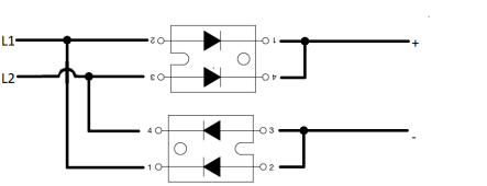
btw I did find a schematic to hookup the rectifier in the mean time.
It was drawn by someone from another forum. this particular guy also recommended the diodes.
1653851410512.png
He put quite some thought into my problem and came up with the diodes and drawing. And although not the best choice of diodes it was the best one could come up with given the constraints at the time.
Maximum respect

Da BAWS for the win
 
Last edited:
Yes my fellow country man. All good thoughts for sure.

Yet where I get my cells from gives me a very narrow time frame in where I can complain if cell bought are not as sold. hence the need to go hard... fast...

And as I intend to but a lot of cells per purchase. Think of 16 to 32 a time then going the normal slow route is not going to cut it unless we dedicate our 100% time n it. I can;t do than I am afraid.

No I need a way to see if cells are what they are sold as in a quick manner.
If they are sold as 280 amps dischargeable and 140 amps chargeable then I want to see it it is true. And fast at that ;)

I mean I am buying them as brand new grade A no funny chinglise tricks cells. I need to make sure they are indeed that.
I get what you mean.
To get exactly 140A charge current will be very difficult to get it right, I think getting 280A discharge is easier, but still not so easy you are talking about 1KW per cell you have to "put somewhere" maybe you can put 12 100W 0.15 ohm resistors parallel and throw them in a big bowl of water, that will give arround 280Amps at 3,6V (battery under load will have a voltage drop, that will change the values a bit, maybe 10x 0.12ohm in parallel, you can add more to get more current)
for a big discharge i have considered water cooled resistive heating

and fantasy device of peltier which cool the hot side with cold side to dissipate a lot of power with less need to use air for excess

thanks for posting
 
While I’m interested to see what you come up with as a fun side project, if anyone is serious about charging a 48v pack at high currents I’d look into buying telecom rectifiers off eBay or Alibaba. I have a Huawei R4850G2 and it will run circles around Signature Solars junk charger.

For $100ish you can get a very high quality 3kw charger. It will do 56amps at 240/230v or 28 amps at 120v and you can set custom output voltage and current limits over CAN.
 
While I’m interested to see what you come up with as a fun side project,
Thank you for your contribution.

While I do have side projects (3d printer) this is not one of them.

This is in realtion to charging at 125 amps (with BMS) /140 amps (without BMS). So I am not sure I follow your suggestion. Did I miss the relevance? if so please rephrase
 
Back
Top