diy solar

diy solar

DIY 304Ah EVE cells with Daly 250A BMS

Lippasti

New Member
Joined
Feb 4, 2022
Messages
6
Hi all,

as a long time reader and now, first time poster, I have just built my first LiFePo4 battery with 304Ah Eve cells. Find below some pics and specs. Happy for any constructive feedback or if anyone spots a mistake. The battery is intended for our offroad vehicle

  1. EVE 304AH cells with rubber foam in between cells as spacer
  2. Daly 250A BMS & active balancer (can optionally be plugged in if I notice too much cell drift)
  3. Double bus bars, taped & with plastic cover on the screws (positive terminal also has one but wasn't on the photo)
  4. Custom fabricated metal housing
  5. Pack tied with filament tape and hollow-chamber plastic board (no idea what this is called in english) as insulator against the housing (visible in the lid)
Generally, I tried to insulate and separate everything as much as possible to avoid any damage caused by vibration and subsequent shortening.

(Very conservative) BMS Settings:
  • High-voltage: 3,4V (Total: 13,6V)
  • Low-voltage: 2,85V (Total: 11,4V)
  • Diff voltage: 0,26V
  • Balance open start voltage: 3.0V
  • Balance open diff voltage: 0.05V
  • Chg high temp protect: 42°C
  • Chg low temp protect 3°C
  • disChg high temp protect: 55°C
  • disChg low temp protect: -15°C

I do have some questions though:
  1. The laser welded studs seem to have a very small surface contact area. What is the maximum amperage they can handle?
  2. The Daly 250BMS only has a 2AWG wire which seems a bit low for currents up to 250A. Do you see any issues on running a continuous 2-2.3kW (150-170A) load?
  3. There is a very minor voltage between the main positive terminal and the case but no voltage between each of the cells and the case. So my suspicion is, that this is from the BMS being screwed onto the case. Do you think this is an issue?


43173536fx.jpg


43173548oj.jpg


43173561vk.jpg
 
Looks good, the only thing I would be worried about is cell movement with the solid buss bars. The cells have a lot of mass and going over rough terrain, washboard roads, pot holes will make them move around. I have an off road application as well and mounted my two 280ah batteries on rubber vibration mounts. I would monitor the connections.
 
Looks good, the only thing I would be worried about is cell movement with the solid buss bars. The cells have a lot of mass and going over rough terrain, washboard roads, pot holes will make them move around. I have an off road application as well and mounted my two 280ah batteries on rubber vibration mounts. I would monitor the connections.

Hi,

thanks for your feedback. Do you mean movement between the cells or for the whole cell pack within the case?
The pack has rubber foam layers between the cells and I wrapped it with like 20-25 rounds of filament tape as strong as I could. There wasn't any movement at all when picking it up, rotating it, etc.
As for the entire pack within the case: It's pretty jam packed in. I had to bend open the case on the top slightly to be able to drop the cell pack in since it was too wide. Once the batter is in place, I will ratched strap it down so hopefully, that will also push the case walls against the insulation further increasing the compression.
We have about 90-95% regular road use and maaaaybe 5-10% offroad and also not crazy heavy. But will definitely make sure to monitor the connections (y)
 
There is a very minor voltage between the main positive terminal and the case but no voltage between each of the cells and the case. So my suspicion is, that this is from the BMS being screwed onto the case. Do you think this is an issue?
I guess it's because the shell is metal, maybe you can test if the metal has a weak voltage
 
he may mean cell expansion

You may enjoy this thread
https://diysolarforum.com/threads/d...cell-holder-springy-contraption-things.18627/

also, I would wonder why you have chosen the very conservative voltage
Then I can't quite follow. One would be the cell expansion and compression during charging/discharging for longevity. Given that the metal case size is what it is, I can really only compress them with the filament tape which does have a pretty strong tensile strenth. So hopefully, this will not allow the cells to expand/contract much during usage. But that expansion/contraction will happen regardless if I use them in a 4x4 rig, a RV or in a stationary setup.

In the reply of @S Davis, he mentiones that the cells will move around due to washboard roads, etc. But that really only can happen for the entire cell block as a whole. But then, the bus bars shouldn't be an issue. Individually, the cells could only move enough to break at the terminals IF the filament tape breaks. If that happens, I will have a problem for sure. But I am quite confident that it will hold up as there is like 25 layers of it wrapped around the cell block as a whole.
Unfortunately, I didn't take a picture of the cell block taped, I guess that would make it a lot easier to explain.

I guess it's because the shell is metal, maybe you can test if the metal has a weak voltage
It's definitely because of the case. But since there is no voltage between the cells directly and the case, it must come from the BMS, which is mounted to the metal case via screws. Question is, is it an issue?
 
Last edited:
Still, Conservative voltage settings?
You're not getting fully charged at those numbers. I had tried low numbers like yours and found I was getting up in the morning with a SOC of 20% - 25%. Not liking that I brought the settings up to the higher recommended numbers and now get up to 79% - 80% SOC.
 
Still, Conservative voltage settings?
You're not getting fully charged at those numbers. I had tried low numbers like yours and found I was getting up in the morning with a SOC of 20% - 25%. Not liking that I brought the settings up to the higher recommended numbers and now get up to 79% - 80% SOC.
Interesting. Those numbers were roughly based on the SOC charts I found here in the forum. My plan is to keep the battery between 10-90% SOC for longevity. Guess I will have to play around a bit and cycle test it a few times with slightly adapted settings until I hit the sweetspot.

It listed 3.32V as 90% SOC so I figured 3.4V would be plenty.

Found the charts in this thread.
 
I have 3 comments. #1, You probably can't "pull" filament tape, even using multiple loops, tight enough to create worthwhile pressure on those battery cells. Eve's "compression test" results call for 12-16 PSI. I don't know the exact size of those cells in inches, but when you do the math (Length * Width of the large cell face in square inches, *12 pounds per square inch) you probably end up with around 600 pounds. That's going to need bolts and compression plates, your box doesn't have room for that while keeping the BMS on the end.

#2, If you configure Daly to shut down at 3.55 volts per cell, but also set the balancing start voltage lower (maybe 3.40 per cell), charging will fall into "balancing mode" very early. Daly BMS provides only tiny amounts of balancing current, and it will favor the lower cells. In balancing mode, it would probably need multiple days of charging for all the cells in your pack to reach 3.55 Volts. (That's why people hate trying to use Daly BMS for balancing).

#3, your plan to allow 10% SOC at the low end hurts battery lifespan a lot. You should try to stop at around 15%, before the voltage starts to fall so quickly. If you look at various sales sites tables of lifespan versus depth of discharge, they don't even bother to limit charging to less than 100% - the tables ALL focus on the depth of discharge. Although most of those tables include a value for 100% depth of discharge (0% SOC) with a poor number total lifespan cycles, hardly any bother to go below even 20% SOC in other rows.

I've concluded from those various tables that it looks much better to go from 100% to 20% on a regular basis, than to do the same while running SOC between 90% and 10%. That's only conclusions drawn from the tables, I've not yet seen any degradation within my own battery packs. (They are 2 and 3 years old, respectively.) are I red-line them at 15%, and almost never go as low as shutdown.
 
Last edited:
Interesting. Those numbers were roughly based on the SOC charts I found here in the forum. My plan is to keep the battery between 10-90% SOC for longevity. Guess I will have to play around a bit and cycle test it a few times with slightly adapted settings until I hit the sweetspot.

It listed 3.32V as 90% SOC so I figured 3.4V would be plenty.

Found the charts in this thread.
Exactly my thoughts BUT, They need to be CHARGED at a higher voltage to get full. Like a 12 volt FLA battery needs to be charged at 14.8 once the charging is removed they will settle down to 12.8ish volts. I know its completely different chemistry but the same idea when it comes to charging.
I may be corrected or clarified here by others as I am relatively new to lithium type batteries. I am just relating to my experience with my set up.
That's correct. But the above numbers are cell voltage masured by the BMS, not the voltage set at the charger. So by the time they reach those voltages on cell level, they should have the respective SOC if I am not mistaken.
I have 3 comments. #1, You probably can't "pull" filament tape, even using multiple loops, tight enough to create worthwhile pressure on those battery cells. Eve's "compression test" results call for 12-16 PSI. I don't know the exact size of those cells in inches, but when you do the math (Length * Width of the large cell face in square inches, *12 pounds per square inch) you probably end up with around 600 pounds. That's going to need bolts and compression plates, your box doesn't have room for that while keeping the BMS on the end.

#2, If you configure Daly to shut down at 3.55 volts per cell, but also set the balancing start voltage lower (maybe 3.40 per cell), charging will fall into "balancing mode" very early. Daly BMS provides only tiny amounts of balancing current, and it will favor the lower cells. In balancing mode, it would probably need multiple days of charging for all the cells in your pack to reach 3.55 Volts. (That's why people hate trying to use Daly BMS for balancing).

#3, your plan to allow 10% SOC at the low end hurts battery lifespan a lot. You should try to stop at around 15%, before the voltage starts to fall so quickly. If you look at various sales sites tables of lifespan versus depth of discharge, they don't even bother to limit charging to less than 100% - the tables ALL focus on the depth of discharge. Although most of those tables include a value for 100% depth of discharge (0% SOC) with a poor number total lifespan cycles, hardly any bother to go below even 20% SOC in other rows.

I've concluded from those various tables that it looks much better to go from 100% to 20% on a regular basis, than to do the same while running SOC between 90% and 10%. That's only conclusions drawn from the tables, I've not yet seen any degradation within my own battery packs. (They are 2 and 3 years old, respectively.) are I red-line them at 15%, and almost never go as low as shutdown.
#1 You're absolutely right, I can definitely not compress them at that rate. But to be fair: neither can any of the plastic cases that these cells are often in when buying ready made batteries. Maybe they will degrade a bit faster if they are not compressed but I can live with that. This is for our 4x4 camper which we maybe use 30-60 days/year if we're lucky and we cycle the battery maybe once every 1-2 days. That means 15-30 cycles/year and if I assume a lifespan of 1500cycles for the cells, that is still a lifespan of 10 years. So degradation due to lack of compression is not my worry. I am strictly trying to prevent them from getting damaged by moving around and for that, the filament tape should hopefully be sufficient.

#2 Regarding balancing mode: In the video where solar garage tested the Daly BMS balancing function, the balancing was reducing the charging current for the three highest cells by 30mA. The way I understood it the implication on charging the cells is so small, that you can set the balancing open voltage quite low with your overall pack still charging pretty much normally. At 30mA difference between the lowest and the three highest cells, this should not have any significant effect on the charging duration. But this should be quite easy to test. Set high open voltage and do a full cycle, then set low open voltage and do a full cycle.

#3 Ok guess I will conduct some additional research. As mentioned in #1, if we can get 8-10 years out of them, I am more than happy. So I figured I might use settings that give me enough power for our needs without killing them too quickly. Will look into the ideal SOC again.
 
Last edited:
The top two numbers are your target for charging cut off. once you get to these numbers your voltage will settle after charging stops. Lower setpoints seem to have much lower SOC results. Just going by my own experience. I'm afraid of giving bad info beyond this.

Capacity %Pack VoltageCell Voltage
100%14.603.65
99%14.453.61
95%13.873.46
90%13.303.32
80%13.253.31
70%13.203.30
60%13.173.29
50%13.133.28
40%13.103.27
30%13.003.25
20%12.903.22
17%12.803.20
14%12.503.12
9%12.003.00
0%10.002.50
 
Hi all,

as a long time reader and now, first time poster, I have just built my first LiFePo4 battery with 304Ah Eve cells. Find below some pics and specs. Happy for any constructive feedback or if anyone spots a mistake. The battery is intended for our offroad vehicle

  1. EVE 304AH cells with rubber foam in between cells as spacer
  2. Daly 250A BMS & active balancer (can optionally be plugged in if I notice too much cell drift)
  3. Double bus bars, taped & with plastic cover on the screws (positive terminal also has one but wasn't on the photo)
  4. Custom fabricated metal housing
  5. Pack tied with filament tape and hollow-chamber plastic board (no idea what this is called in english) as insulator against the housing (visible in the lid)
Generally, I tried to insulate and separate everything as much as possible to avoid any damage caused by vibration and subsequent shortening.

(Very conservative) BMS Settings:
  • High-voltage: 3,4V (Total: 13,6V)
  • Low-voltage: 2,85V (Total: 11,4V)
  • Diff voltage: 0,26V
  • Balance open start voltage: 3.0V
  • Balance open diff voltage: 0.05V
  • Chg high temp protect: 42°C
  • Chg low temp protect 3°C
  • disChg high temp protect: 55°C
  • disChg low temp protect: -15°C

I do have some questions though:
  1. The laser welded studs seem to have a very small surface contact area. What is the maximum amperage they can handle?
  2. The Daly 250BMS only has a 2AWG wire which seems a bit low for currents up to 250A. Do you see any issues on running a continuous 2-2.3kW (150-170A) load?
  3. There is a very minor voltage between the main positive terminal and the case but no voltage between each of the cells and the case. So my suspicion is, that this is from the BMS being screwed onto the case. Do you think this is an issue?


43173536fx.jpg


43173548oj.jpg


43173561vk.jpg
Can you provide the BMS number please.
You state low temp protect? This must be a new BMS if so. I like the 250amps.
Thanks.
 
Can you provide the BMS number please.
You state low temp protect? This must be a new BMS if so. I like the 250amps.
Thanks.

Hi,
it's the current generation of Daly 250A BMS. It should be this one.

Seems to work pretty well so far. Since it is possible to set the temperature, I'll test it by setting the low-temp charge protect slightly above ambient temperature and see, if it closes the charge MOS. If it does, I'd also trust it will do it if set to freezing temp.

But there is YT videos where this is being tested and it seems to work just fine.
Will there be an 8s in the model? Looks like a great option. Big help!
 
First post here, and trying to learn as much as possible before starting my own build.

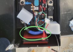
I like your custom made box, iI just wanted to point out one thing that concerns me. The routing of your b- wire is pushed against your heatsink. Maybe they are at the same potential, but those cooling fins will eventually rub through the insulation on that wire, and that could get nasty if they aren’t at the same potential.D1563FC4-55DE-48D3-8E8B-4DF7D353471D.jpeg
 
Hello all,
Shopping EVE cells.
Any of these suppliers reliable?
18650
Docan
Alibaba

Thanks!
 
What do you mean?
18650 is a form factor
Alibaba is a platform.

It's like asking what is the best paint?
1 gallon
Rust-oleum
Home Depot

Do a search here, plenty of writing about Docan, Luyuan, Basen, Qishou just to name a few in no particular order
 
As I have said- I’m a newbie in all ways to this. I saw a header that looked like a supplier title showing 18650?
I now have pricing from Docan. I think that’s where I’m going. US warehouse. Fast ETA.
Learning:).
 
18650 had a store on Aliexpress, it was a scam. You are correct that 18650 was a supplier.

Docan may not be the cheapest but if you are looking for cheap, I would suggest you change your search parameters to reliable. Docan will be right up there on that list.
 
Back
Top