LazyCanadian
New Member
- Joined
- Sep 2, 2020
- Messages
- 13
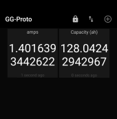
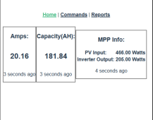
I’ve made my own amp meter using a Raspberry Pi Zero W, an ads1115 chip and a 300 amp shunt. It seems pretty accurate and I’ve been checking it’s readings against my Overkill BMS readings.
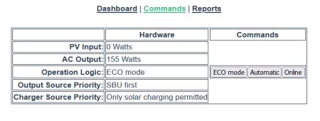
I’ve also got the pi sending commands to my PIP1012LV-MK so now I can control it’s settings based on the state of charge of my battery bank. This gives a lot of options to get some interesting behavior out of my All-in-one.
I live in BC so I want to keep my battery pretty high during the winter in case of power outage and increase the range of discharge in the summer. I am also planning a solar divert circuit that can switch to run additional load when it’s really sunny and the battery bank is getting close to full. This unit won’t be powerful enough for a fridge but I am probably going to get a bigger one soon.
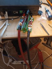
Here's a picture of the shunt, I 3d printed a case to keep it together. Under the desk is a DIY 272ah lifepo4 battery.

I'm a java developer for my day job, working with hardware to make the shunt was pretty fun. The driver is written in Python and I'm using MQTT events to send data between the different components. I'll post updates on my UI work as I make progress, going to be using VueJS.
To talk to the PIP1012LV-MK I have been using this python project https://github.com/jblance/mpp-solar. It's a great project and it introduced me to MQTT.
I’ve also got the pi sending commands to my PIP1012LV-MK so now I can control it’s settings based on the state of charge of my battery bank. This gives a lot of options to get some interesting behavior out of my All-in-one.
I live in BC so I want to keep my battery pretty high during the winter in case of power outage and increase the range of discharge in the summer. I am also planning a solar divert circuit that can switch to run additional load when it’s really sunny and the battery bank is getting close to full. This unit won’t be powerful enough for a fridge but I am probably going to get a bigger one soon.
Here's a picture of the shunt, I 3d printed a case to keep it together. Under the desk is a DIY 272ah lifepo4 battery.

I'm a java developer for my day job, working with hardware to make the shunt was pretty fun. The driver is written in Python and I'm using MQTT events to send data between the different components. I'll post updates on my UI work as I make progress, going to be using VueJS.
To talk to the PIP1012LV-MK I have been using this python project https://github.com/jblance/mpp-solar. It's a great project and it introduced me to MQTT.


