I plan covered version with rotational mirror and liquid lens, this is fast hack to make pcb sometimes. Emitted power is about 20mW diverging, no access to system except me. But fixed red plexi box around beam up to focal point should be doable..I'd drop a cover over it. Interlocked.
Invisible beam.
Add a camera for monitoring, or a viewport with suitable filters.
Refer to the safety triangle, you're at the point, "PPE".


You are using an out of date browser. It may not display this or other websites correctly.
You should upgrade or use an alternative browser.
You should upgrade or use an alternative browser.
DIY BMS design and reflection
- Thread starter BiduleOhm
- Start date
Hedges
I See Electromagnetic Fields!
- Joined
- Mar 28, 2020
- Messages
- 20,628
Only 20 mW? Or average, and pulse higher? You're blowing copper off!
If it really dropped to 0.5 mW or something at operator distance that would make a difference. But by "diverging", not sure the cone angle. We saw specs regarding distance at which power dropped to a safe level.
I saw various lasers on Amazon, some for cutting wood or whatever rated several watts.
We were warned of "laser pointers" worded to make it past the safety censor, but with pictures of lighting things on fire.
We have similarly hazardous but limited access equipment, and after I nearly electrocuted myself, EH&S has clamped down further. Locked room and qualified workers wasn't enough for them.
Lasers make me nervous because they can reach out further, if shiny objects are involved.
NoOnly 20 mW? Or average, and pulse higher? You're blowing copper off!
If it really dropped to 0.5 mW or something at operator distance that would make a difference. But by "diverging", not sure the cone angle. We saw specs regarding distance at which power dropped to a safe level.
I saw various lasers on Amazon, some for cutting wood or whatever rated several watts.
We were warned of "laser pointers" worded to make it past the safety censor, but with pictures of lighting things on fire.
We have similarly hazardous but limited access equipment, and after I nearly electrocuted myself, EH&S has clamped down further. Locked room and qualified workers wasn't enough for them.
Lasers make me nervous because they can reach out further, if shiny objects are involved.
") I'm only exposing photoresist and then using HCl+H2O2
I'm only exposing photoresist and then using HCl+H2O2To blow copper off you need pulsed NIR, we tried 6kW/pulse (300W average) fiber laser and this was finally enough to evaporate reflective Cu. But this one MUST be fully enclosed because my friend got reflected beam which created nice hole in full face shield.
I also have blue 5W, and with this one I'm more cautious because it is capable to impair my eyes permanently. It can cut balsa wood, paper etc


I tested cap-fet voltage limiter, it almost works but I forget there will be inductive spike from cap's inductance (you can see it at +4us) which triggers COMP again. The voltage below is at film capacitor (50uF/800V/1.6kA max), in FET drain is resistor 50mR. The current after fet ON is 800A and it is interesting how the initial part of its discharge is masked by its resistive drop (it has 8mR ESR). Hysteresis is set as to discharge cap by 12V before stopping - it seems ok except there is need to add about 300ns LEB after turn off. I have no more time to hack some 74123 to it but the overall behavior shows it is viable way. At 100 pulses/sec only resistor is at 60C, FET (IPTG014N10N) is about 35C.
I also added extra RC 1k/1n before R4 and 51V TVS to FET.

I'll not pursue this design further at this time as for my energy levels it is simpler and cheaper to add bunch of TVS, but if I would do bigger BDU where inductive kicks are over 20J I'd finish it because by using EUR8 caps you can scale to approx 50J/1kA/cap with 20V overshot.
Hedges
I See Electromagnetic Fields!
- Joined
- Mar 28, 2020
- Messages
- 20,628
No
In that case, how are you processing and disposing of the waste stream?
Sewage treatment plant gets fined if their bugs die and raw sewage is discharged into the waterways.
Do you turn around and use it for pattern plating?
Just evaporate away the water?
I have one container for organics (acetone, spend IPA) and another for anorganics (acids and NaOH plus some bicarbonate soda). I drive them to municipal facility twice per year.. Ehh to be precise - last time I forgot to close organics and it evaporatedIn that case, how are you processing and disposing of the waste stream?
Sewage treatment plant gets fined if their bugs die and raw sewage is discharged into the waterways.
Do you turn around and use it for pattern plating?
Just evaporate away the water?
View attachment 170869 View attachment 170871
I tested cap-fet voltage limiter, it almost works but I forget there will be inductive spike from cap's inductance (you can see it at +4us) which triggers COMP again. The voltage below is at film capacitor (50uF/800V/1.6kA max), in FET drain is resistor 50mR. The current after fet ON is 800A and it is interesting how the initial part of its discharge is masked by its resistive drop (it has 8mR ESR). Hysteresis is set as to discharge cap by 12V before stopping - it seems ok except there is need to add about 300ns LEB after turn off. I have no more time to hack some 74123 to it but the overall behavior shows it is viable way. At 100 pulses/sec only resistor is at 60C, FET (IPTG014N10N) is about 35C.
I also added extra RC 1k/1n before R4 and 51V TVS to FET.
View attachment 170872
I'll not pursue this design further at this time as for my energy levels it is simpler and cheaper to add bunch of TVS, but if I would do bigger BDU where inductive kicks are over 20J I'd finish it because by using EUR8 caps you can scale to approx 50J/1kA/cap with 20V overshot.
Very nice! Thanks for the testing
Happy New year to all. I've got a few days to play with BMS again so that I did new 2 channel version:

and tested it during short on inverter side. The red clip is the short. I have set my limiter circuit do 150A and this is result:

Current was rising into short up to 150A, then FET (SIR582) breaks the cicuit (0.3us response time), it continues to rise to 166A and then we see voltage overshot from 9uH cable inductance. There are 3pcs 8.0SMDJ51A in parallel and they clamp voltage to 74V. Usable for 80V FETs.
For sake of pulse measurement I simulated battery by big pulse rated capacitor and measured overshot by active high voltage differential probe:

I'll do other measurements (steady 50A ON state, battery side short) but it feels quite robust now.
M.
and tested it during short on inverter side. The red clip is the short. I have set my limiter circuit do 150A and this is result:
Current was rising into short up to 150A, then FET (SIR582) breaks the cicuit (0.3us response time), it continues to rise to 166A and then we see voltage overshot from 9uH cable inductance. There are 3pcs 8.0SMDJ51A in parallel and they clamp voltage to 74V. Usable for 80V FETs.
For sake of pulse measurement I simulated battery by big pulse rated capacitor and measured overshot by active high voltage differential probe:
I'll do other measurements (steady 50A ON state, battery side short) but it feels quite robust now.
M.
Bidule, still here ?
I designed 10kW FOC motor drive and wanted to look what aluminium backed PCB can offer. I've done 40x40mm halfbridge with 5xSIR582, 8x 2u2/100V X7R, 1mR/15W current sense, NTC temp sensor and 3 massive milled M4+M5 brass electrodes:


Driver and differential current amp is on smaller PCB on top of it. The alum PCB is interesting experience - I've needed to coat it by photoresist using fan as centrifuge, expose by laser and etch in ammonium persulfate so that it doesn't eat aluminium...
I connected 9uH (made from 16mm2 wire) and run it in buck-mode from 48V.
It can go up to 160A continuous (at 20kHz) - the loss of alum PCB is 90W then (it is about 7.5kW output with 98% eff) and MOSFETs are about 100 deg.celsius:


Not bad for such small/cheap pcb.
So .. it seems the Al PCB is nice way to make hi-power devices. I'll replace 5x6mm SO8 FET by larger 8x8mm package - it can be seen that main problem is to get heat down thru alumina isolator - as large footprint as possible if needed.
I publish this mainly to help others with similar designs.
Regarding BMS, it is interesting test to show that it is BIG problem to use regular PCB for current >50A. See here for 4layer 2oz version of FOC driver above with extra Cu wire soldered to main traces to keep resistance down:

This is 50A current for 1minute (there is big heatsing on other side). The heating goes from both FETs and from Cu traces. Busbars are neccessity here - split current to smaller chunks and let em add together on busbar only.
M.
I designed 10kW FOC motor drive and wanted to look what aluminium backed PCB can offer. I've done 40x40mm halfbridge with 5xSIR582, 8x 2u2/100V X7R, 1mR/15W current sense, NTC temp sensor and 3 massive milled M4+M5 brass electrodes:
Driver and differential current amp is on smaller PCB on top of it. The alum PCB is interesting experience - I've needed to coat it by photoresist using fan as centrifuge, expose by laser and etch in ammonium persulfate so that it doesn't eat aluminium...
I connected 9uH (made from 16mm2 wire) and run it in buck-mode from 48V.
It can go up to 160A continuous (at 20kHz) - the loss of alum PCB is 90W then (it is about 7.5kW output with 98% eff) and MOSFETs are about 100 deg.celsius:
Not bad for such small/cheap pcb.
So .. it seems the Al PCB is nice way to make hi-power devices. I'll replace 5x6mm SO8 FET by larger 8x8mm package - it can be seen that main problem is to get heat down thru alumina isolator - as large footprint as possible if needed.
I publish this mainly to help others with similar designs.
Regarding BMS, it is interesting test to show that it is BIG problem to use regular PCB for current >50A. See here for 4layer 2oz version of FOC driver above with extra Cu wire soldered to main traces to keep resistance down:
This is 50A current for 1minute (there is big heatsing on other side). The heating goes from both FETs and from Cu traces. Busbars are neccessity here - split current to smaller chunks and let em add together on busbar only.
M.
Last edited:
Warpspeed
Solar Wizard
Just found this thread, and it makes for a truly fascinating read.
I went through all of this myself a while back, and ended up with a few alternative solutions some of which have not been discussed here so far.
As I run thirty cells here (100v nominal), commercial analog multiplexer chips were not an option for me.
Multiplexers are a very good solution at lower voltages though.
The trend today seems to be towards higher dc voltage systems.
My approach for switching cell voltages onto a common bus was to use LAA127 opto isolated mos relays.
https://www.alldatasheet.com/datasheet-pdf/pdf/488715/IXYS/LAA127.html
Finding an ADC that has sufficient accuracy and resolution, is not difficult, but I found a much larger problem was the noise level at each cell introduced by a hard working inverter plus HF ripple from various solar controllers.
Its not difficult to bench test a system and measure nice clean cell voltages, but in a real working environment, for me, the voltage measurements danced around all over the place due to noise voltages caused by high cell ripple current.
Software averaging requires too many samples and a settling time far too long to be practical, especially when cycling through a large number of cells in a higher voltage system. There are ways around that, but I came up with a different and more successful approach.
What I use now, is a voltage to frequency converter instead of a conventional analog to digital converter.
A significant advantage for me, is there is only one "bit" to opto isolate in a fully floating voltage measurement front end.
The V/F converter can be fully isolated and directly measure cell voltages via the mos relay multiplexer.
Now the trick here, is that any noise on the cell voltage just causes frequency modulation on the output. No filtering or integration required prior to the V/F converter. The frequency counts are then accumulated over a reasonable period in a counter. The final count will be the AVERAGED frequency over the measurement interval, no matter how crazy the induced noise.
If the measurement period is made an exact multiple of the inverter period (or extremely close) that offers even higher potential noise reduction.
Its also pretty easy to accumulate a very large number of counts over a fairly short measurement interval. In other words a very high resolution reading is theoretically possible.
The accuracy mainly comes down to design of the V/F converter and temperature drift of the timing capacitor.
With a bit of care and some testing pretty good results are possible.
The Ham Radio guys have experience building temperature stable VFOs, the results can be as good as the effort put into it.
For our application, absolute accuracy is much less important than being able to measure very small differences between individual cells, and to do it repeatedly and noise free with rock steady resolution down to one millivolt. The V/F technique is cheap, fast, and the results far better and more stable than I was ever able to achieve either by analog filtering, or software averaging with a conventional A/D converter.
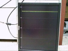
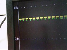
As far as displaying cell voltages, a video histogram far more readily shows up any cell that is way out of whack with the others.
A quick glance at the screen tells you the whole story without having to really think too much about it.
I have one video screen at the battery out in the shed, and another video monitor in my kitchen.
The XVGA video was all generated in hardware, and the pictures are a lot brighter and sharper than the fuzzy pictures below suggest.
And it was a lot easier to generate with much less video bandwidth with the monitor rotated into portrait mode.
My camera is broken at the moment (I dropped it some time ago) and all I have are some pretty crappy and now rather ancient fuzzy pictures I took during original testing of just the video board.
The graphics are pretty crude, but all the information is right there and easy to see what is going on.
I went through all of this myself a while back, and ended up with a few alternative solutions some of which have not been discussed here so far.
As I run thirty cells here (100v nominal), commercial analog multiplexer chips were not an option for me.
Multiplexers are a very good solution at lower voltages though.
The trend today seems to be towards higher dc voltage systems.
My approach for switching cell voltages onto a common bus was to use LAA127 opto isolated mos relays.
https://www.alldatasheet.com/datasheet-pdf/pdf/488715/IXYS/LAA127.html
Finding an ADC that has sufficient accuracy and resolution, is not difficult, but I found a much larger problem was the noise level at each cell introduced by a hard working inverter plus HF ripple from various solar controllers.
Its not difficult to bench test a system and measure nice clean cell voltages, but in a real working environment, for me, the voltage measurements danced around all over the place due to noise voltages caused by high cell ripple current.
Software averaging requires too many samples and a settling time far too long to be practical, especially when cycling through a large number of cells in a higher voltage system. There are ways around that, but I came up with a different and more successful approach.
What I use now, is a voltage to frequency converter instead of a conventional analog to digital converter.
A significant advantage for me, is there is only one "bit" to opto isolate in a fully floating voltage measurement front end.
The V/F converter can be fully isolated and directly measure cell voltages via the mos relay multiplexer.
Now the trick here, is that any noise on the cell voltage just causes frequency modulation on the output. No filtering or integration required prior to the V/F converter. The frequency counts are then accumulated over a reasonable period in a counter. The final count will be the AVERAGED frequency over the measurement interval, no matter how crazy the induced noise.
If the measurement period is made an exact multiple of the inverter period (or extremely close) that offers even higher potential noise reduction.
Its also pretty easy to accumulate a very large number of counts over a fairly short measurement interval. In other words a very high resolution reading is theoretically possible.
The accuracy mainly comes down to design of the V/F converter and temperature drift of the timing capacitor.
With a bit of care and some testing pretty good results are possible.
The Ham Radio guys have experience building temperature stable VFOs, the results can be as good as the effort put into it.
For our application, absolute accuracy is much less important than being able to measure very small differences between individual cells, and to do it repeatedly and noise free with rock steady resolution down to one millivolt. The V/F technique is cheap, fast, and the results far better and more stable than I was ever able to achieve either by analog filtering, or software averaging with a conventional A/D converter.
As far as displaying cell voltages, a video histogram far more readily shows up any cell that is way out of whack with the others.
A quick glance at the screen tells you the whole story without having to really think too much about it.
I have one video screen at the battery out in the shed, and another video monitor in my kitchen.
The XVGA video was all generated in hardware, and the pictures are a lot brighter and sharper than the fuzzy pictures below suggest.
And it was a lot easier to generate with much less video bandwidth with the monitor rotated into portrait mode.
My camera is broken at the moment (I dropped it some time ago) and all I have are some pretty crappy and now rather ancient fuzzy pictures I took during original testing of just the video board.
The graphics are pretty crude, but all the information is right there and easy to see what is going on.
Attachments
curiouscarbon
Science Penguin
- Joined
- Jun 29, 2020
- Messages
- 3,022
opto isolated mos multiplexing cell voltages to a voltage to frequency converter and taking care to characterize the temperature/frequency curve of the (crystal) time oscillator sounds like a really clever architecture for scaling up relative cell measurements up to higher system voltage levels.
measurement interval being configured to integer multiple of ripple current also nice for reducing artifacts.
great point about ease of passing the "PWM" signal and ease of reading
measurement interval being configured to integer multiple of ripple current also nice for reducing artifacts.
great point about ease of passing the "PWM" signal and ease of reading
I used rather cheap CPC1025N for this. But later I realized it is better to use dedicated multichannel chips interconnected by RS485 or xformers. Yes you are right about hi-voltage trend. We stick with 48-60V mainly because of Infini inverters.The trend today seems to be towards higher dc voltage systems.
My approach for switching cell voltages onto a common bus was to use LAA127 opto isolated mos relays.
https://www.alldatasheet.com/datasheet-pdf/pdf/488715/IXYS/LAA127.html
Nice idea to use V/F.Its not difficult to bench test a system and measure nice clean cell voltages, but in a real working environment, for me, the voltage measurements danced around all over the place due to noise voltages caused by high cell ripple current.
..
What I use now, is a voltage to frequency converter instead of a conventional analog to digital converter.
A significant advantage for me, is there is only one "bit" to opto isolate in a fully floating voltage measurement front end.
The V/F converter can be fully isolated and directly measure cell voltages via the mos relay multiplexer.
I like to use AMC1035 or AMC1100 - these are sigma delta modulators and their (isolated) 1bit stream can be decoded by MCU to 14bit precision. And because of noise shaping properties they are quite immune to out of band noise and by sinc filtering you get the averaging effect.
Also e.g. STM32H750 has dedicated sinc filter for it and it can give 16bits at 70ksps and also out-of range (overcurrent) indication in 1us..
You can place them near to source (current shunt) and then route 1bit to controller. Another way I use is use MCP6D11 to amplify diff signal and route it differentially all the way to MCU ADC.
The ISL94216 I use for battery cells has stable reading to 0.3mV level even under inverter load.
Or its integer multiple... sampled V/F is equivalent to running sum filter which has deep nulls at frequencies corresponding to sum time.Now the trick here, is that any noise on the cell voltage just causes frequency modulation on the output. No filtering or integration required prior to the V/F converter. The frequency counts are then accumulated over a reasonable period in a counter. The final count will be the AVERAGED frequency over the measurement interval, no matter how crazy the induced noise.
If the measurement period is made an exact multiple of the inverter period (or extremely close) that offers even higher potential noise reduction.
Insane. Thats the interesting part. Do you generate it as analog RGB or DVI/HDMI ? FPGA ? I got older screen so that I've written Verilog code to generate 1600x900 HDMI just out of curiosity:As far as displaying cell voltages, a video histogram far more readily shows up any cell that is way out of whack with the others.
A quick glance at the screen tells you the whole story without having to really think too much about it.
I have one video screen at the battery out in the shed, and another video monitor in my kitchen.
The XVGA video was all generated in hardware, and the pictures are a lot brighter and sharper than the fuzzy pictures below suggest.


but it never comes to my mind to use it as battery state
Warpspeed
Solar Wizard
https://www.renesas.com/us/en/document/dst/isl94216-datasheet?r=1322681The ISL94216 I use for battery cells has stable reading to 0.3mV level even under inverter load.
That has everything we could possibly wish for in a 16 cell monitoring system.
Never knew that chip even existed. It might be well worth a look for many here.
Quite a few solutions for sixteen cells, but when you have more cells than that, off the shelf options start to become much more limited.
I have built several of these cell monitoring systems from time to time, and they all worked.
But I kept having fresh ideas that I just had to try.
It sounds like you might suffer from the same obsession
When I finally achieved rock solid noise free readings of 1mV resolution, that was good enough.
V/F converter is just a humble AD654 with a 1% polystyrene timing capacitor.
Its bare bones RGB + H&V sync all hardware generated with basic 5v logic gates and counters.Do you generate it as analog RGB or DVI/HDMI ? FPGA ?
There is an interesting website (Tiny VGA.com) that lists all the VGA standards, of which there are a great many.
An absolute must have if you wish to build yourself a nuts and bolts video generator.
A great project if you are a hardware masochist !
http://tinyvga.com/vga-timing
A completely software approach using an old PC or laptop, would be a much more sensible way to go about it.
My skills are more in the hardware design side of things.
It was an interesting challenge, something I have thought about doing for a long time.
Don't want to hijack this thread with video generators.
You can find scalable offerings from Renesas and TI whose can be interconnected using pulse transformers tohttps://www.renesas.com/us/en/document/dst/isl94216-datasheet?r=1322681
That has everything we could possibly wish for in a 16 cell monitoring system.
Never knew that chip even existed. It might be well worth a look for many here.
Quite a few solutions for sixteen cells, but when you have more cells than that, off the shelf options start to become much more limited.
form high voltage packs. I was trying to roll own version with cheapo opamp per cell and PNP current source
to level shift them to lowest cell but still there dedicated chips win from both price & complexity standpoint
DefinitelyI have built several of these cell monitoring systems from time to time, and they all worked.
But I kept having fresh ideas that I just had to try.
It sounds like you might suffer from the same obsession
In fact many of my geek friends do. I see it as good property except when one feels he needs to try something so badly that his other work suffers yeah.. I understand, great challenge and one learns things on the way.There is an interesting website (Tiny VGA.com) that lists all the VGA standards, of which there are a great many.
An absolute must have if you wish to build yourself a nuts and bolts video generator.
A great project if you are a hardware masochist !
http://tinyvga.com/vga-timing
My current must-to-do-myself is the FOC driver for 72V/200A IPM motor. I already figured all parts including actual HB design (above) but now I'm struggling how to do DC busbar. Because of skin effect I have to work with 1mm Cu (probably 20x1 mm2), keep them together to minimize inductance but I need to "somehow" fix six 40x18x7.5mm radial capacitors to them and still allow some flexture (thermal expansions as caps are fixed on Al heatsink). Then I need to connect the busbars to three HBs (again flex conns because of expansion) - the best way I come to is simple 6mm2 wire with M4 ring electrodes. These will have 60uohm for 20mm length - some 1W of heat for 150A...
Any ideas ?
M.
Last edited:
Warpspeed
Solar Wizard
One advantage of being an old bugger, retirement provides a lot of time to chase technical fantasies aroundI see it as good property except when one feels he needs to try something so badly that his other work suffers
How about some kind of laminated multilayer structure, something like flat planar Litz wire ?I'm struggling how to do DC busbar. Because of skin effect I have to work with 1mm Cu (probably 20x1 mm2)
Home made multilayer sandwich made from thin copper sheet, with a sheet of high temperature insulation between layers.
That would allow some flexure, and should have pretty good HF properties.
Should be possible to go thinner than 1mm with more layers.
Copper layers can be soldered or spot welded together along one edge only for connections.
I think we should try really hard to stay on topic
Last edited:
Similar threads
- Replies
- 8
- Views
- 339
- Replies
- 11
- Views
- 568
- Replies
- 8
- Views
- 287
- Replies
- 15
- Views
- 511